Summary of A pic programmer circuit based on AN589
This article describes a reliable parallel port PIC programmer circuit based on Microchip's AN589 application note. It details the schematic, PCB layout, and safety precautions for connecting to a computer's parallel port. Key modifications include adding transmission line termination for long cables, using an LM317 voltage regulator for 11.6V output, incorporating a power steering diode, upgrading the 5V regulator to an LM78L05, adding an ICSP connector and power LED, swapping the 74LS244 for a 74HCT244, and standardizing resistors to 10k ohms.
Parts used in the Parallel Port PIC Programmer:
- LM317 voltage regulator
- LM78L05 3pin 100mA regulator
- Power supply steering diode
- ICSP connector
- LED indicator
- 74HCT244 chip
- 10k resistors
- Parallel port cable
AN589 is microchip’s application note for a parallel port pic programmer circuit which I chose as I wanted something reliable to get up and running quickly.
It is really quite a simple circuit and its main objective is to provide ICSP connections to your pic microcontroller.
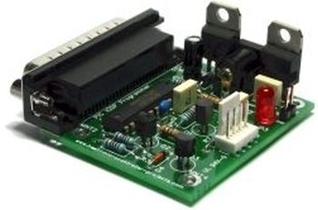
Here is the pcb version (click to enlarge):
Note: That the PGM signal is not provided – it’s not really necessary anyway as you can turn off PGM mode by programming the chip. For first use of a chip you will need to pull the PGM line low as PGM is enabled by the manufacturer.
PIC Programmer Circuit diagram
Click on the following diagram to open it as a PDF document.
Disclaimer : If you build this circuit you must double check each connection to the parallel port cable to avoid damage to your computer. This includes checking for shorts between each pin at the parallel port on your circuit. For initial testing it is best if you use a spare (old computer). Building this project is your own responsibility and I can not be held responsible for any damage to your computer.
Modifications
It has a few modifications that are useful and easy to do:
- Transmission line termination – lets it work over a long cable.
- LM317 voltage regulator to get 11.6 volts and protect the circuit
- Power supply steering diode (stops you reverse connecting the supply).
- Changed LM340-5 to 3pin 100mA LM78L05.
- ICSP connector.
- An LED to show that power is applied.
- Changed 74LS244 to 74HCT244 because I had one handy!
- Standard 10k resistors instead of 2k – just easier if they are all the same.
Circuit notes
Transmission line termination
The transmission line termination lets you use the pic programmer circuit at the end of a long cable – I am using a normal parallel cable ~6 feet long. If you want to know more about transmission line terminations then follow this link.
When I first tried to use it I got all kinds of random results so it is worth adding the termination.
Power supply regulators
The LM317 saves you needing an accurate bench power supply – you can use a dc power block – anything that supplies more than about 15V dc. If you don’t use a 317 it’s just too easy to accidentally apply the wrong voltage by turning the dial on a bench supply and frying your microchip. Using the 317 lets you put up to 35V into it (you shouldn’t but you can).
Note: the LM317 and LM78L05 are standard components and are easy to find.
For more detail: A pic programmer circuit based on AN589
- Why is transmission line termination necessary?
It allows the circuit to work reliably over long cables, such as a 6-foot parallel cable. - What voltage does the LM317 regulator provide?
The LM317 is used to generate 11.6 volts for the circuit. - Can I use a bench power supply without the LM317?
No, it is risky because accidentally setting the wrong voltage can fry the microchip. - What is the purpose of the power supply steering diode?
It prevents damage by stopping the user from reverse connecting the power supply. - Why was the 74LS244 changed to a 74HCT244?
The change was made simply because the author had a 74HCT244 chip handy. - How do you initially disable PGM mode on a new chip?
You must pull the PGM line low during the first use since it is enabled by the manufacturer. - What input voltage range can the LM317 handle?
The LM317 can accept up to 35V into it, though higher voltages are not recommended. - Why were 2k resistors replaced with 10k resistors?
Standard 10k resistors were used because they are easier to source when all values are the same.