Summary of A brief overview of Allegro ACS712 current sensor. Part 2 – Interface the sensor with a PIC microcontroller
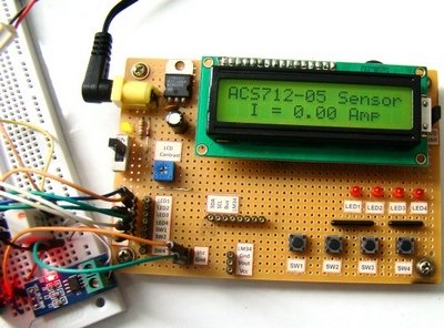
This article details building a DC current meter using an ACS712-05B sensor and a PIC16F1847 microcontroller. The system measures analog voltage output via the ADC, processes it with firmware to calculate current, and displays results on an LCD. It highlights the ratiometric nature of the sensor, which maintains accuracy despite supply voltage fluctuations, but notes the 26.4 mA resolution limit makes it unsuitable for low currents without external amplification.
Parts used in the DC Current Meter:
- ACS712-05B breakout module
- PIC16F1847 microcontroller
- 16×2 character LCD
- 2.7 Ω (rated 2 Watt) resistor
- Varying DC voltage source
- 1 nF filter capacitor
- 100 nF decoupling capacitor
- PIC16F1847 breadboard module
- Experimenter's I/O board
In the first part of this discussion, the features of ACS712 device were briefly discussed. Now we will use that theory to implement the ACS712 sensor to make a simple DC current meter. The analog output voltage from the sensor is measured through an ADC channel of the PIC16F1847 microcontroller. A voltage to current conversion equation will be derived and implemented in the firmware of the PIC microcontroller and the actual load current will be displayed on a character LCD.
Experimental circuit setup
We are going to setup a test experiment to demonstrate the use of ACS712 to measure a DC current. I am using an ACS712-05B breakout module (you can find them cheap on ebay) for this purpose.
 It has got a 1 nF filter capacitor connected between pin 6 and ground, a 100 nF decoupling capacitor between power supply lines, and a power on LED soldered on the board. The power supply and output lines are accessible through header pins on one side, whereas, the current terminals are connected to a 2-pin terminal block on the opposite side, as shown below.
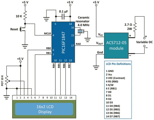
The experimental circuit diagram of the DC current meter is shown below. A 2.7 Ω (rated 2 Watt) resistor is connected in series with the current terminals and a varying dc voltage is applied to vary the current through the resistor and the current path. The output of the sensor module goes to AN0 (pin 17) ADC channel of the PIC16F1847 microcontroller. A 16×2 character LCD is used to display the measured current output.
I am using my PIC16F1847 breadboard module along with the Experimenter’s I/O board to demonstrate this experiment.
The microcontroller uses the supply voltage (+5V) as reference for A/D conversion. The digitized sensor output is processed through software to convert it to the actual current value. The mathematics involved in the process is described in the white board below.
For Vcc=5V and ADC Vref=5V, the relationship between output voltage and ADC Count is
![]()
But,
![]()
![]()
![]()
Important note: The calculations shown above considered supply voltage Vcc = Vref = 5.0 V. Interestingly, the final equation relating I and Count remains the same even the power supply fluctuates. For example, suppose Vcc fluctuates and becomes 4.0 V. Then, the sensitivity of the ACS712-05B also changes to 0.185 x 4/5 = 0.148 mV.
 If you repeat the above calculations with Vcc = Vref = 4.0 V and sensitivity = 0.148 mV, you will end up with the same equation for I and Count. This was possible because of the ratiometric output of the ACS712 sensor.
The equation clearly tells that the current resolution for this setup is 26.4 mA, which corresponds to count 513, one count higher than the zero current offset. Therefore, this kind of arrangement is not suitable for measuring low current. You need an external Op-Amp circuit to enhance the resolution and be able to make more sensitive current measurement. If you are interested on that, you can visit Sparkfun’s ACS712 Low Current Sensor Breakout page that provides a circuit diagram for such an arrangement.
For more detail: A brief overview of Allegro ACS712 current sensor. Part 2 – Interface the sensor with a PIC microcontroller
- How is the current value calculated?
The digitized sensor output is processed through software firmware to convert the ADC count into the actual current value. - Does the equation change if the power supply fluctuates?
No, the final equation relating current and count remains the same even if the power supply fluctuates due to the ratiometric output. - What is the current resolution of this setup?
The current resolution is 26.4 mA, which corresponds to count 513. - Can this arrangement measure low currents accurately?
No, this arrangement is not suitable for measuring low current because of its limited resolution. - How can sensitivity be enhanced for low current measurement?
An external Op-Amp circuit must be added to enhance the resolution and enable more sensitive measurements. - Which ADC channel is used for the sensor output?
The output of the sensor module goes to AN0, which is pin 17 of the microcontroller. - What reference voltage is used for A/D conversion?
The microcontroller uses the supply voltage of +5V as the reference for A/D conversion. - What happens to the sensor sensitivity if Vcc drops to 4.0 V?
The sensitivity changes to 0.148 mV, but the calculation equation for current remains identical.