
Summary of Small Virtual Wall for iRobot Roomba using PIC12F629
This article describes a compact circuit mimicking the iRobot Virtual Wall using a PIC12F629 microcontroller. Designed with SMD components to fit a 9V battery, it emits an infrared pattern (0xA2) modulated at ~38-40KHz to block Roomba robots. The system uses an RC oscillator and a MIC5205 regulator for power efficiency.
Parts used in the Small Virtual Wall for iRobot Roomba:
- PIC12F629 Microcontroller
- MIC5205-5 Voltage Regulator
- Infrared LED
- Visible Light LED
- R1 Resistor (for RC oscillator)
- C6 Capacitor (for RC oscillator)
- R6 Resistor (for frequency adjustment)
- 5-pin Header (for programmer connection)
- 9V Battery (PP3/6F22)
The Virtual Wallis a circuit to mimic the behaviour of the iRobot Virtual Wall/Lighthouse, provided with the robot. It produces the same infrared pattern and the robot sees it as another virtual wall, blocking its path, while vacuuming.
This circuit was built mostly using SMD components to reduce its size, nearly to the size of a 9V battery (PP3/6F22/6LF22/etc).
Design Considerations
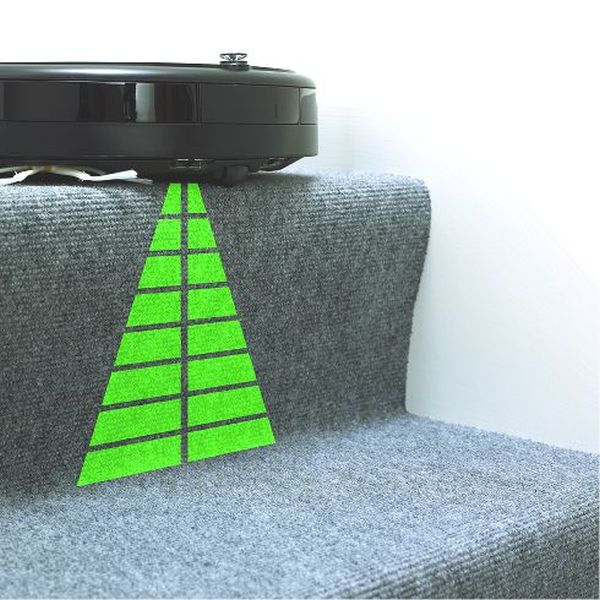
After examining the original virtual wall, with a webcam, I was able to see that it emits infrared light from its top round transparent ring and from a small hole above the switches. The light coming from the top ring prevents the robot from colliding with the virtual wall, if it comes from its sides or from behind. The front hole emits light as a beam. This beam of light is directional and stops at the nearest obstacle, probably a real wall, preventing the robot from crossing it to the other side.
The pattern emitted by the virtual wall is a form of PWM, modulated with a carrier frequency around 38KHz. Below is a picture of the pattern captured using a TSOP1238 and an oscilloscope.
It consists of a sequence of eight bits, encoded as:
So the byte being emitted is 0xA2 or 0b10100010. The pattern repeats itself after a few tenths of milliseconds later.
A circuit to emit a similar pattern will need to output the same 0xA2 pattern, generate the 38KHz carrier frequency and mix the two together. Using a PIC microcontroller it is possible to output the pattern and generate the carrier frequency. Mixing is accomplished by connecting the LED between the PWM output and the carrier output.
A great solution is to use the PIC’s master clock oscillator output to produce the carrier frequency. This is the solution proposed by the circuit below. The PIC clock runs at 160KHz (FOSC) using an RC oscillator and the carrier frequency is available on CLKOUT pin as FOSC/4, at 40KHz.
Schematic
From left to right we see the main switch, the power supply based on a MIC5205-5, 5V/150mA regulator, the microcontroller, two LEDs, one emitting visible light and an infrared one. Connected to the microcontroller’s pin 2 (CLKIN) are R1 and C6 that form the RC pair for the PIC oscillator. There’s also a 5 pin header to connect the programmer (an ICD2 or another compatible one). Click the image to enlarge.
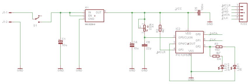
The power supply’s MIC5205 is a low dropout voltage, low noise, low quiescent current, regulator very good for battery powered circuits and powerful enough to deliver 150mA. The circuit consumes 3.5mA on average and the IR LED peak current is 25mA mostly because the PIC cannot drive more than 25mA on its pins. The input voltage should be between 5.2V and 16V and I suggest a 9V battery to which you may hold the circuit using velcro or any double sided sticky tape.
As referred above, the PIC’s master clock should be adjusted to FOSC=160KHz using R1. Connecting a frequency counter to pin 3 (CLKOUT) and adjusting R6 until 39KHz or 40KHz are displayed. This adjustment is not critical.
For more detail: Small Virtual Wall for iRobot Roomba using PIC12F629
-
How does the circuit mimic the original virtual wall?
The circuit produces the same infrared pattern and robot sees it as another virtual wall blocking its path. -
What is the byte pattern emitted by the virtual wall?
The pattern consists of eight bits encoded as 0xA2 or 0b10100010. -
Can I use a standard 9V battery for this project?
Yes, the input voltage should be between 5.2V and 16V, and a 9V battery is suggested. -
How is the carrier frequency generated in this design?
The PIC master clock oscillator output is used to produce the carrier frequency available on the CLKOUT pin. -
What is the function of the R1 and C6 components?
R1 and C6 form the RC pair connected to the microcontroller's pin 2 (CLKIN) for the PIC oscillator. -
Does the circuit consume much power from the battery?
The circuit consumes 3.5mA on average which is suitable for battery-powered circuits. -
What tool is needed to adjust the frequency?
A frequency counter is needed to connect to pin 3 (CLKOUT) while adjusting R6 until 39KHz or 40KHz are displayed.
