 Pictures are better readable locally with appropriate viewer, so we suggest download them first
This PIC software combines frequency counter and frequency lock functions. By adding couple of transistors and operation amplifier TL082, it is possible to lock the LC oscillator frequency.
Let’s look at the following block diagram. Software functions are presented inside the dashed area.
Frequency Reference
Frequency reference is formed from the measured frequency itself after the delay defined by parameter 0Dh, when the number of the consecutive samples (defined by 0Eh) of measured frequency are within the +/-20 Hz. Then the actual value is trigged as frequency reference until the SW detects that the lock conditions are not valid.
Frequency Actual
Frequency actual is formed from the frequency counter function itself.
Subtraction and Comparator
Frequency is measured every 100 ms. Next the frequency actual is subtracted from the reference and the difference is compared to value zero to calculate the deviation. If the result is zero, it means that no deviation and also no need to fine-tune the oscillator frequency.
If the result is negative it means that the frequency actual is higher than reference. This detects the direction of the needed frequency correction. Next the rough value of the difference is calculated. If within 20 Hz then only short 2.4 ms pulse is controlled. If bigger then 100 ms pulse is controlled. By means of these few calculations we have information how to fine-tune the frequency of the oscillator to hold the frequency actual equal as frequency reference. Simple, is it?
Digital Outputs
These pulses are controlled to digital outputs RB0 or RB3 according to the sign of the frequency difference. The outputs are never simultaneously on because it means almost short circuit.
Integrator
The controller is made using TL082 operation amplifier. The first amplifier is an integrator by means of the capacitor C8 and R23. A time constant is R23 * C8 = 22 M Ohms * 2.2 uF = 48 s. So the control is slow and it only fine tunes the oscillator frequency and this is of course the purpose of the controller. The VFO itself must be stable enough. Second amplifier of TL082 is connected as a buffer.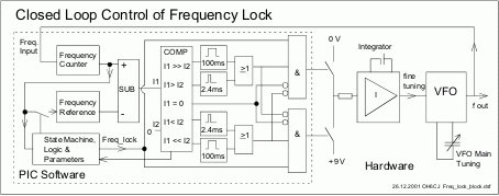
Transistors Q2…Q4
If the PIC SW controls the output RB0 to state TRUE, then led D4 is light and Q2 saturates. It connects integrator input via R23 to GND and the voltage at the output pin 1 changes to positive direction. If the RB3 is controlled to state TRUE, D4 is light and Q3 connects the base of the Q4 to ground. As a result Q4 is saturated and +9 V is connected to the R23. Now output changes to negative direction. If none of RBs are controlled, the integrator acts an analogue memory. It holds the last value at the output. This suites well for the situation where the subtraction result of reference and actual is zero. The used transistor types are not critical.
For more detail: PIC Frequency Counter with Frequency Lock function