
Summary of Basics of LED dot matrix display. Part 1. Theory using pic microcontoller
This article explains the basic structure of a monochrome LED dot matrix and its interface with a microcontroller for displaying static text. It details how wiring LEDs in rows and columns reduces I/O pin requirements from 64 to 16 in an 8×8 setup, enabling character display through column scanning.
Parts used in the LED Dot Matrix Display Project:
- Monochrome (single color) LED dot matrix
- Microchip PIC18F2550 microcontroller
- StartUSB for PIC board
LED dot matrices are very popular means of displaying information as it allows both static and animated text and images. Perhaps, you have encountered them at gas stations displaying the gas prices, or in the public places and alongside highways, displaying advertisements on large dot matrix panels. In this experiment, we will discuss about the basic structure of a monochrome (single color) LED dot matrix and its interface with a microcontroller to display static characters and symbols. We will cover the animation stuff in next tutorial.
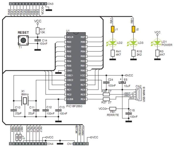
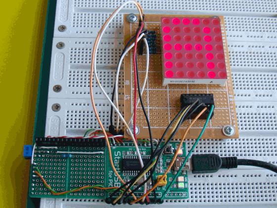 I am using the Microchip PIC18F2550 microcontroller on the StartUSB for PIC board for demonstration, but this technique is applicable to any other microcontrollers that have sufficient I/O pins to drive the LED matrix.
Theory of LED dot matrix display
In a dot matrix display, multiple LEDs are wired together in rows and columns. This is done to minimize the number of pins required to drive them. For example, a 8×8 matrix of LEDs (shown below) would need 64 I/O pins, one for each LED pixel. By wiring all the anodes together in rows (R1 through R8).
 and cathodes in columns (C1 through C8), the required number of I/O pins is reduced to 16. Each LED is addressed by its row and column number. In the figure below, if R4 is pulled high and C3 is pulled low, the LED in fourth row and third column will be turned on. Characters can be displayed by fast scanning of either rows or columns. This tutorial will discuss the method of column scanning.
For more detail: Basics of LED dot matrix display. Part 1. Theory
-
What is the primary advantage of wiring LEDs in rows and columns?
It minimizes the number of pins required to drive the LEDs. -
How many I/O pins are needed for an 8x8 matrix if wired individually?
An 8x8 matrix would need 64 I/O pins if one was used for each LED pixel. -
How does the reduced pin count work in an 8x8 matrix?
By wiring anodes together in rows and cathodes in columns, the requirement drops to 16 pins. -
Which microcontroller is used in this demonstration?
The Microchip PIC18F2550 microcontroller on the StartUSB for PIC board is used. -
Can this technique be used with other microcontrollers?
Yes, it is applicable to any microcontroller with sufficient I/O pins to drive the matrix. -
How is a specific LED turned on in the matrix?
An LED is addressed by pulling its specific row high and its specific column low. -
What method does this tutorial use for displaying characters?
This tutorial discusses the method of column scanning. -
Does this article cover animated text displays?
No, animation is covered in the next tutorial.
