Summary of PIC Based Car Battery Voltage Monitoring System
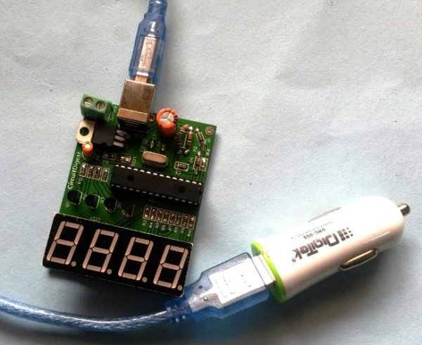
This project details a PIC-based Car Battery Monitoring System built on a custom PCB using EasyEDA. Designed to plug into a car's USB outlet or cigarette lighter, the circuit monitors battery voltage (up to 15V) during charging or standby modes. It features a four-digit seven-segment display for readings and includes a terminal block to measure external power sources like power banks or adapters, helping users detect faulty charging systems.
Parts used in the PIC Based Car Battery Voltage Monitoring System:
- PIC Microcontroller PIC18F2520
- Fabricated PCB Board
- USB connector
- 2 pin Terminal Connector
- Common anode seven segment display(4 in 1)
- BC557 Transistor
- 1k resistor
- 2k resistor
- 100R resistor
- 1000uF capacitor
- 10uF capacitor
- 28 pin IC base
- female burgsticks
- 7805 Voltage regulator
- Car USB charger
- LED
- Zener diode5.1v
- USB cable (B-type or Arduino UNO compatible)
- 20MHz Crystal
- 33pF capacitor
In this project we are going to make a PIC based Car Battery Monitoring system on PCB. Here we have designed a PCB using EASYEDA online PCB simulator and designer. This Car Battery Monitoring Circuit is used to monitor the power of Car Battery by just plugging it into the power outlet on the dashboard of a car. The PCB also has the option to use it as Voltage Measurement tool or Voltmeter without using USB car charger. We have attached a terminal block here to measure the voltage of other power sources, just by connecting two wires in it from the power source.
Components Required:
- PIC Microcontroller PIC18F2520 -1
- Fabricated PCB Board -1
- USB connector -1
- 2 pin Terminal Connector (optional) -1
- Common anode seven segment display(4 in 1) -1
- BC557 Transistor -4
- 1k resistor -6
- 2k resistor -1
- 100R resistor -8
- 1000uF capacitor -1
- 10uF capacitor -1
- 28 pin IC base -1
- female burgsticks -1
- 7805 Voltage regulator -1
- Car USB charger -1
- LED -1
- Zener diode5.1v -2
- USB cable (B-type or Arduino UNO compatible) -1
- 20MHz Crystal -1
- 33pF capacitor -2
Description:
Generally it is not important to measure the car battery power every time, but we often need to know about battery voltage during charging, to check whether its charging or not. By this, we can protect battery failure due to the faulty charging system. The voltage of a 12v car battery during charging is about 13.7v. So we can identify whether our battery is charging well or not and can investigate the causes of battery failure. In this project, we are going to implement a Voltage Meter for Car Battery by using a PIC microcontroller. Car Cigarette Lighter or Car USB charger is used for getting the battery voltage to the ADC pin of the microcontroller with the help of Voltage Divider Circuit. Then a 4 digit seven segment display is used to show the voltage value of battery. This circuit can measure the voltage up to 15v.
When a car battery is charging, then the voltage across the battery terminals is actually coming from the alternator/rectifier, that’s why system reads 13.7 volts. But when the battery is not charging or car’s engine is not ON, then the voltage across battery terminal is actual battery voltage around 12v.
We can also use the same circuit for measuring the voltage of other power sources up to 15v. For this purpose we have soldered the Terminal Block (green color plastic block) in PCB where you can connect two wires from power source and can monitor the voltage. Check the Video at the end, where were we have demonstrated it by measuring the voltage of a Variable power Supply, a USB power bank and a 12v AC-DC adapter. Also check the Simple Battery Monitor Circuit and 12v Battery Charger Circuit.
Circuit Diagram and Working Explanation:
In this Battery Voltage Monitoring Circuit, we have read car battery voltage by using an inbuilt analog pin of PIC microcontroller and here we have selected pin AN0 (28) pin of microcontroller through a voltage divider circuit. A zener diode of 5.1v is also used for protection.
For more detail: PIC Based Car Battery Voltage Monitoring System
- What is the primary function of this system?
The system monitors car battery power by plugging into the dashboard power outlet. - Can this device be used as a voltmeter without a USB car charger?
Yes, the PCB has an option to use it as a Voltage Measurement tool without the charger. - How does the circuit protect the microcontroller input pin?
A zener diode of 5.1v is used for protection alongside a voltage divider circuit. - What is the maximum voltage this circuit can measure?
This circuit can measure the voltage up to 15v. - Does the system read different voltages when the engine is running?
Yes, it reads about 13.7 volts when charging from the alternator versus around 12 volts when not charging. - How can you measure the voltage of other power sources?
You connect two wires from the power source into the soldered terminal block on the PCB. - Which specific pin of the microcontroller is used for reading voltage?
The system uses pin AN0 (pin 28) of the microcontroller through a voltage divider circuit. - What components are used to display the voltage value?
A 4 digit common anode seven segment display is used to show the voltage value.