
Summary of F84 Miniature Real-Time Controller
This article describes the F84 MRTC, a low-power real-time controller using a PIC16F84 microcontroller driven by a 32.768Hz crystal. It features a 6-channel scheduler stored in EEPROM, allowing daily tasks to be preprogrammed via Nigel PicProg without serial downloading. The system includes battery backup for clock operation and programmable time setting via a button.
Parts used in the F84 Miniature Real-Time Controller:
- PIC16F84 Flash based RISC uController
- 32,768Hz low power X-tal
- EEPROM (64-byte data space)
- Nigel PicProg software
- Two AA size batteries (+3V backup)
- 74LS07 open collector buffer
- Silicon signal diode (1N914 or 1N4148) as D1
- Ge diode with lower V forward as D2
- Momentary switch S1
- Small LED at RB0
Build a simple real-time controller with PIC16F84 running at low power X-tal 32,768Hz. Daily scheduler for 6-channel resided in 64-byte EEPROM can easily be preprogrammed using Nigel PicProg.
RTC2.C provides user programmable set current time without the need of recompilation.
Fixed bug on minute conversion! Introduction
 RTC2.C provides user programmable set current time without the need of recompilation.
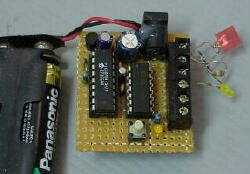 The F84 MRTC was my second design of a miniature real-time controller. This version uses PIC16F84 running with a low power X-tal 32,768Hz. The scheduler for 6-channel output was saved in EEPROM. No terminal for serial downloading of the scheduler. It’s suitable for fixed scheduler job. Two AA size battery provides +3V backup for clock operation when main power has failed. Time setting at 19:00 is set only once by pressing S1 button. The 6-channel open collector output provides max. 30mA @30V load.
Hardware
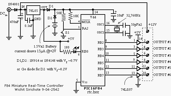
A circuit diagram of the F84 MRTC is shown in Figure 1. The controller is PIC16F84, Flash based RISC uController running with a low-power X-tal 32,768Hz. The 6-channel output is RB2 to RB7 connected to a 74LS07 open collector buffer providing approx. 30mA @30V suitable for driving a homemade opto-triac shown in Miniature Real-time Controller 2051 version. D1 and D2 forms a simple switch between main supply and +3V battery. As can be seen, D1 may be silicon signal diode 1N914 or 1N4148. D2, however, can use a Ge diode having lower V forward. S1 is a momentary switch when pressed, it set current time to 19:00. The small LED at RB0, indicates functioning of the controller, after reset the blink rate is 1Hz, after press S1 set time to 19:00, it will blink at 1/3Hz or every 3 second.
Software
The original source program for the F84 MRTC was written using ‘C’, RTC.C with header file RTC.H. The hex file, RTC.HEX was compiled by PICC PCW V2.666. Daily scheduler is resided in 64-byte EEPROM data space. Editing for your scheduler can be made under PicPro by Nigel Goodwin. As shown in Figure 2, each byte may edit and enter into Nigel’s Picpro buffer before write the code and EEPROM data into the F84 chip. See details of setting scheduler in RTC.C.
For more detail: F84 Miniature Real-Time Controller
- What microcontroller is used in the F84 MRTC?
The controller uses a PIC16F84, which is a Flash based RISC uController. - How is the daily scheduler programmed?
The scheduler can be edited and entered into Nigel's PicPro buffer before writing the code and EEPROM data into the chip. - Can the current time be set without recompilation?
Yes, RTC2.C provides user programmable set current time without the need of recompilation. - What components form the switch between main supply and +3V battery?
D1 and D2 form a simple switch between main supply and +3V battery. - What type of diode should be used for D2?
D2 can use a Ge diode having lower V forward. - How does the LED indicate the controller status after pressing S1?
After pressing S1 to set time to 19:00, the LED blinks at 1/3Hz or every 3 seconds. - What compiler was used to compile the hex file?
The hex file was compiled by PICC PCW V2.666. - Does this design require a terminal for serial downloading?
No, there is no terminal for serial downloading of the scheduler as it is suitable for fixed scheduler jobs.

