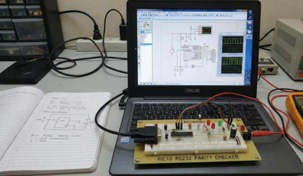
Summary of PIC10 RS232 Parity Checker using PIC10F202 with Proteus Simulation
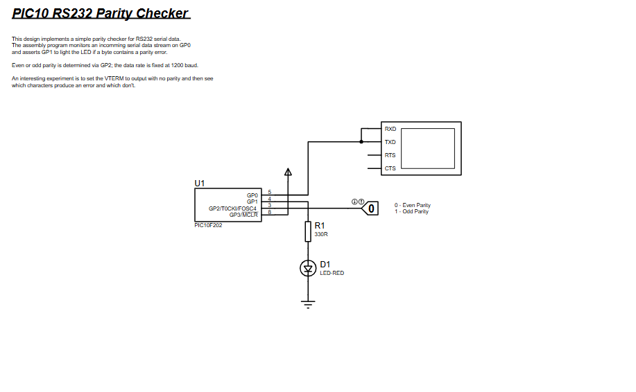
The PIC10 RS232 Parity Checker uses a PIC10F202 to sample RS232 serial data bit-by-bit in software, count data ones, and verify parity (even/odd via GP2). GP0 receives serial bits, GP1 drives an LED on parity error, and timing delays emulate UART sampling. The project is demonstrated in Proteus VSM with a virtual terminal, illustrating timing-critical sampling and parity validation on a minimal microcontroller.
Parts used in the PIC10 RS232 Parity Checker:
- PIC10F202 Microcontroller
- RS232 terminal (Proteus VTERM)
- LED (error indicator)
- 330Ω resistor
- Power supply and ground connections
- Why is there no hardware UART used in this project?
The PIC10F202 does not include a hardware UART, so serial communication is implemented in software. - Can this project work with different baud rates?
The baud rate is fixed by delay timing values in the code and would need recalibration to change. - How is even or odd parity selected?
Parity mode is selected using the GP2 input pin. - Why is Proteus ideal for this project?
Proteus allows accurate timing simulation and easy RS232 terminal testing without physical hardware. - Can this code run on other PIC10 devices?
It is specifically written for the PIC10F202 but can be adapted to similar PIC10 devices. - What happens if no parity bit is sent?
Characters without parity will often trigger errors, making this a useful experiment. - Can the LED logic be inverted?
Yes, the GPIO output logic can be modified to invert LED behavior. - Is this suitable for real hardware testing?
Yes, with proper RS232 level shifting, the design can be implemented on physical hardware.