Summary of Pic Cross Development Support Tools
The author adapted a machine-independent SMAL assembler into a PIC assembler for 14-bit PICs and built a Linux-capable PIC programmer called SNOPPP (Son of NOPPP). SNOPPP adds diode-generated marginal voltages, a transistor for stable Vpp, a clock terminator for in-circuit programming, and a custom Linux driver that implements Microchip adaptive burner logic. Distribution includes source, headers, manuals, schematics, photos, and a UNIX shell archive for tools and driver.
Parts used in the SNOPPP:
- C source code for SMAL-based PIC assembler
- Header files and concise manual (documentation)
- Shell archive packaging
- Resistor network (white dual-inline package with 3K resistors)
- 1N4003 diodes (array for marginal voltages)
- Transistor for programming voltage supply (Vpp)
- LED indicator
- 3M DipClip and 8-inch ribbon cable (programming clip)
- 14-pin socket for programmer cable
- Schematic and PCB or perfboard components as per schematic
- Parallel port interface (hardware wired to D0, D1, etc.)
- Clock line terminator components (as integrated in SNOPPP)
The SMALpic Assembler
When I embarked on a substantial PIC-based project for paid work, I encountered a common issue: most of the PIC tools were designed exclusively for Windows. Additionally, the Linux tools available seemed to require a significant time investment to upgrade my outdated Linux system. However, I already had a capable assembler at my disposal in the form of the machine-independent SMAL assembler.
I decided to devote a few days to adapting this assembler into a PIC assembler. This newly adapted tool is written in C, employs a command-line interface, and is virtually free from system dependencies, apart from the necessity of having a C compiler. There is no need for the latest versions of lex, yacc, make, or any other similar tools.
This assembler is designed to process code for all 14-bit PIC microcontrollers, and it includes files specifically tailored for the PIC16C72, PIC16C73, PIC16C74, PIC16C76, and PIC16C77. (I happened to be working on code for the 16C76.)
The distribution of the code comes in the form of a shell archive, encompassing source code, header files, and a concise manual.
The SNOPPP Pic Programmer
All the commercial PIC programmers I came across were primarily designed for Windows, but I needed a solution that could work seamlessly with Linux. So, I began my search for a suitable programmer. The NOPPP from Covington Innovations seemed promising, prompting me to construct my version, the NOPPP-2, which utilized an IC instead of a handful of diodes in the original design. However, I encountered some issues when using it with UV EPROM-based PICs for several reasons:
First, it lacked the critical feature of a marginal voltage check necessary for producing high-quality PIC programmers. This entails programming with a 5-volt supply and then reading back the program using a 5.6-volt supply and a 3.8-volt supply to verify the programming’s quality. To address this, I incorporated an array of 1N4003 diodes to generate these essential voltages.
Second, the programming voltage Vpp required for the UV EPROM-based PICs needed to fall within a narrower range than that of the flash EEPROM PICs. They demanded precisely 14.0 volts, but I empirically determined that 13.8 volts worked as well. Furthermore, programming the UV EPROM versions appeared to draw significant power from the 14-volt programming supply, making it unsuitable to have a series resistor between the regulator and the chip. Consequently, I introduced an additional transistor into the programming voltage supply. This had the effect of inverting the programming signal to the NOPPP, necessitating modifications to the driver code.
I’ve named my adapted NOPPP the “Son of NOPPP,” or SNOPPP for short. Below, you’ll find the schematic and a photograph of the final product:
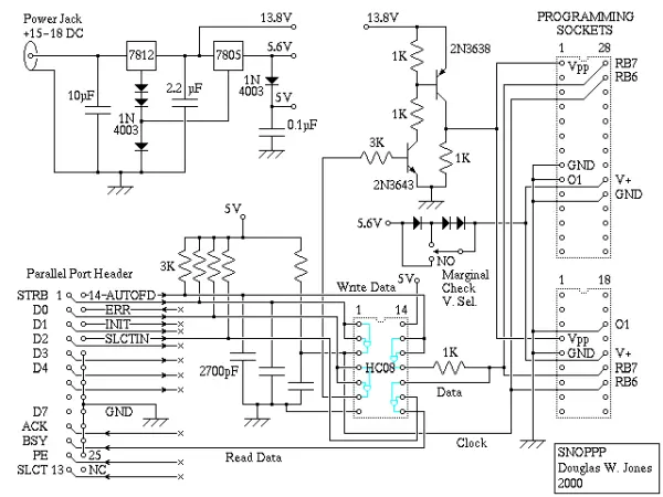
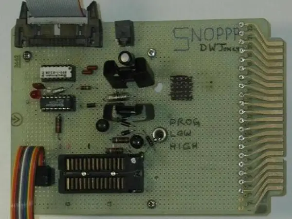
Following the ethos of the initial NOPPP, I constructed my SNOPPP by repurposing spare components. Among the components at my disposal was a resistor network, and you can spot all the 3K resistors illustrated in the diagram within the white dual-inline package situated at the upper left of the image. With some extras available, I decided to employ one for an indicator light, as depicted in the photo with the LED.
In-Circuit programming with the SNOPPP
It’s worth mentioning that I utilize this programmer for in-circuit programming. I use a 3M DipClip attached to the end of an 8-inch ribbon cable for the programming process. To ensure reliable operation, I found it necessary to include a clock line terminator for the PIC. I integrated the terminator within the SNOPPP device rather than the cable assembly, making it a simple plug-and-play solution when connecting it to the SNOPPP socket for in-circuit programming.
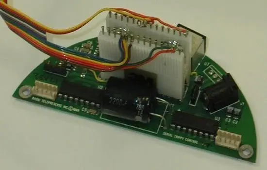
The schematic for the programming clip intended for 28-pin PICs is displayed here, while the photo illustrates the clip I actually used, securely fastened to a PIC16C76 on the motor control board I was tasked with developing. My programmer cable comes with a dedicated 14-pin socket, and ideally, I should have designed it to connect directly to the programmer using a header that matches the same pinout as the PIC, as indicated in the schematic.
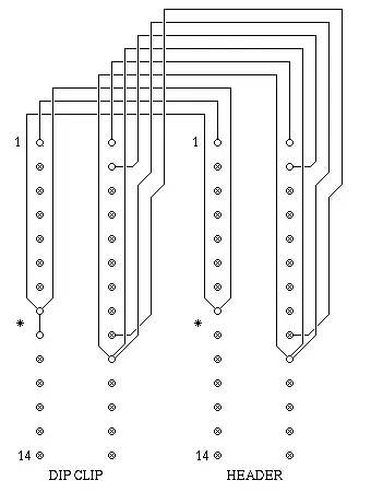
Please be aware that when using this in-circuit programming method, the programmer supplies power not only to the PIC but to all components connected to the same +5 supply circuit as the PIC. It is crucial to exercise caution in the circuit design to ensure this does not create any issues. Additionally, when applying power to the PIC, it will resonate if a crystal oscillator or ceramic resonator is attached. To prevent this, the programming clip grounds the O1 pin. This grounding is also present on the programmer’s socket, but it is advisable to ground it locally with a short jumper (indicated by an asterisk in the schematic) rather than using a lengthy wire.
Another point to note is that the cable configuration is designed in a way that each signal wire is flanked on both sides by ground wires, providing some level of shielding.
A Linux Driver for the SNOPPP
The Linux driver software for the SNOPPP is provided in the form of a UNIX shell archive. Installing this driver requires root privilege, as it circumvents the standard driver for the parallel port and directly interfaces with the hardware.
This driver has undergone testing specifically with the 16C76, but it should theoretically function with other 14-bit Flash EEPROM PICs if you specify them as 16C76 chips. Additionally, it still includes Covington’s code for supporting the 16C84, 16F84, and 16F83 chips, although this functionality remains untested.
Apart from modifying the original NOPPP driver to reverse the Vpp line, I had to make adjustments to implement Microchip’s recommended adaptive burner logic for UV EPROM-based PICs. This involves a sequence of programming steps, data verification after each step, and iterative repetitions until the read data matches the data being programmed.
Suggested Enhancements to the SNOPPP
Contemplating the aforementioned issue, it dawned on me that implementing certain hardware adjustments could significantly enhance its performance. For instance, substituting D0 and D1 for Autofd and D0 as output, or employing PE instead of BSY for input, would have allowed me to adapt the system to function seamlessly with the standard LINUX parallel port driver. This, in turn, would eliminate the need for manual configuration, resulting in improved efficiency. However, I refrained from making these alterations because I preferred dedicating my time to revenue-generating activities rather than tinkering with support tools.
It would also be intriguing to employ D2 and D3 for voltage control, enabling the software to execute marginal testing without necessitating manual switching for each verification pass by the user.
Source: Pic Cross Development Support Tools
- What assembler was adapted for PIC development?
The machine-independent SMAL assembler was adapted into a PIC assembler written in C with a command-line interface. - Which PIC devices does the assembler support?
It processes code for all 14-bit PIC microcontrollers and includes files for PIC16C72, PIC16C73, PIC16C74, PIC16C76, and PIC16C77. - Why were 1N4003 diodes used in SNOPPP?
They were used to generate the marginal voltages (5.6V and 3.8V) needed for quality verification of programming. - How was the Vpp requirement for UV EPROM PICs addressed?
A transistor was added to the programming voltage supply to provide a stable ~14.0V (13.8V found acceptable) and to avoid a series resistor between the regulator and the chip. - Can SNOPPP program in-circuit?
Yes; the author uses it for in-circuit programming with a 3M DipClip and included a clock line terminator in the SNOPPP device for reliability. - What caution is advised when using in-circuit programming?
The programmer supplies power to all components on the same +5V circuit, so circuit design must ensure this does not cause issues; the O1 pin is grounded to prevent oscillator resonance. - How is the SNOPPP Linux driver distributed and installed?
The driver is provided as a UNIX shell archive and requires root privilege to install because it bypasses the standard parallel port driver and accesses hardware directly. - Does the SNOPPP driver support other PICs besides 16C76?
It was tested with 16C76 but should work with other 14-bit Flash EEPROM PICs if specified as 16C76; it also contains untested support code for 16C84, 16F84, and 16F83. - What programming logic was implemented for UV EPROM-based PICs?
Microchip's recommended adaptive burner logic was implemented: a sequence of programming steps with data verification after each step and iterative repeats until read data matches programmed data. - What enhancements were suggested for SNOPPP hardware?
Using different parallel port lines to match the standard LINUX driver (e.g., Autofd and PE) and using D2/D3 for voltage control to allow software-driven marginal testing were suggested.