Summary of USB to Serial TTL
This article details a DIY USB to Serial TTL converter built using a PIC 16F1455 microcontroller. The project allows users to connect serial devices to modern computers via USB without needing special Windows drivers, as it utilizes standard Microchip descriptors. It supports variable baudrates (9600–115200) via jumpers and includes an RS232 level-shifting board for compatibility with legacy hardware.
Parts used in the USB to Serial TTL Converter:
- PIC microcontroller 16F1455 with socket
- Ceramic capacitors: 1 * 470 nF, 1 * 100nF, 2 * 22 pF
- Crystal 12 MHz
- Electrolytic capacitor of 10 uF/25V
- Resistors: 2 * 10k, 3 * 330 Ohm, 2 * 22 Ohm
- LEDs: 1 Amber, 1 Yellow, 1 Green
- USB connector
- Jumpers: 2
- Header: 4 pins
For some of my PIC projects I need a serial (RS232) interface to print some messages on the screen of my computer. I still have a desktop computer that has one RS232 interface but nowadays most computers have a USB interface instead. You can buy devices that convert – TTL – RS232 signals to USB for which several projects have already been published on Instructables but I decided to build one myself. The reason for that is that I like building stuff but also that this version does not need a special driver for Windows 10 since it uses a standard Microchip device descriptor which is already supported by Windows 10.
Since the requirements for the baudrate may vary I decided to support the following baudrates using jumpers on the board: 9600, 19200, 57600 and 115200. The device always uses 8 bits, 1 stopbit and no parity for its transmission.
As you may know you cannot use TTL signals to drive an RS232 interface so I also created an RS232 board based on the MAX232 chip that converts the signals to the right level. In this Instructables I have also posted the schematic diagram of the RS232 board since I used it for testing my USB to Serial TTL converter.
I used a PIC 16F1455 as device to control the USB port and transfer all data from USB to serial using the JAL programming language.
Step 1: The Electronics
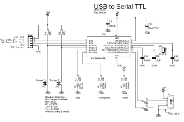
The schematic diagram shows the electronic components you need. Note that I also posted the schematic diagram of the RS2323 board that converts TTL signals to RS232 signals but this is just as extra information. The component list below is only for the USB to Serial TTL converter.
You need the following electronic components for this project:
- 1 PIC microcontroller 16F1455 with socket
- Ceramic capacitors: 1 * 470 nF, 1 * 100nF, 2 * 22 pF
- 1 crystal 12 MHz
- 1 Electrolytic capacitor of 10 uF/25V
- Resistors: 2 * 10k, 3 * 330 Ohm, 2 * 22 Ohm
- LEDs: 1 Amber, 1 Yellow, 1 Green
- 1 USB connector
- 2 Jumpers
- 1 header, 4 pins
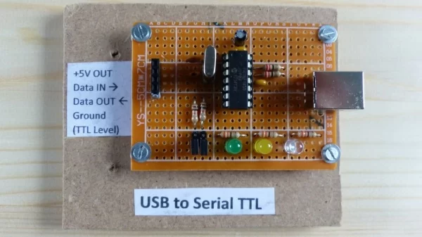
You can build the circuit on a breadboard, as shown in the picture. The circuit is powered by the USB connection. I used the USB 5 Volt for powering the RS232 board.
Step 2: The Software
The software performs the following tasks:
- Handling the USB interface. For this I used a standard JAL USB serial library
- After the USB to Serial TTL converter is configured, the yellow LED will be turned on
- When a character is received from the USB it is copied to the serial interface
- When a character is received from the serial interface it is copied to the USB
- Each time a character is received from either side, the green LED is turned on shortly to indicate data is transfered
- Set the baudrate of the serial interface using the jumper settings. The baudrate can be changed at any moment
Before the USB interface can be used it has to be configured by the host computer. This is done by setting the right serial parameters in the terminal emulator program on the PC and enabling RTS/CTS flow control. The baudrate of the USB interface can be set to any value while the baudrate of the serial interface is determined by the jumper settings. Note that both baudrates do not need to be the same.
The JAL source file and the Intel Hex file for programming the PIC are attached.
Attachments
Step 3: The Final Result
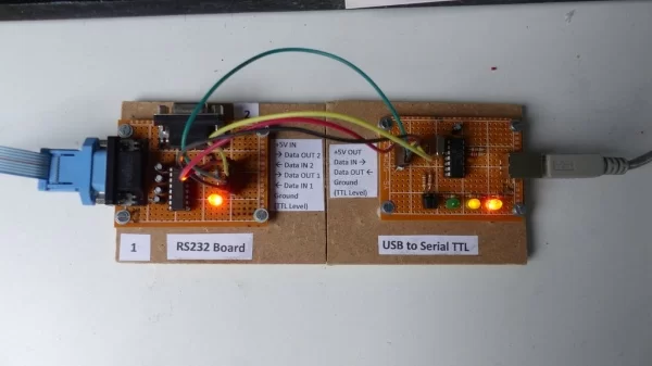
For this demo I connected the USB to Serial TTL converter to my RS232 board. Reason for that is that I can then show the operation on my desktop computer that has both a USB port and an RS232 port.
In the video you see 2 terminal emulator windows open. The left window shows the data on the RS232 port while the right window shows the data on the USB port. For the RS232 port no flow control is needed. For the USB port, the USB to Serial TTL converter is configured by enabling the RTS/CTS flow control after which the yellow LED will turn on.
Note that for this demo I used a baudrate of 9600 baud for the RS232 port and a baudrate of 115200 if the USB port.
If you are interested in using the PIC microcontroller with JAL – a Pascal like programming language – visit the JAL website
Have fun making this Instructable and looking forward to you reactions and results.
Source: USB to Serial TTL
- Why did the author build this device instead of buying one?
The author built it because they enjoy building stuff and this version does not require a special driver for Windows 10. - Which microcontroller is used to control the USB port?
A PIC 16F1455 microcontroller is used to control the USB port and transfer data. - What programming language was used for the software?
The JAL programming language, which is described as a Pascal-like language, was used. - How are the supported baudrates configured?
Baudrates of 9600, 19200, 57600, and 115200 are selected using jumpers on the board. - Can the USB and serial baudrates be different?
Yes, the baudrate of the USB interface can be set to any value while the serial interface baudrate is determined by jumpers. - What flow control is required for the USB port?
RTS/CTS flow control must be enabled in the terminal emulator program on the PC. - What do the LEDs indicate during operation?
The yellow LED turns on when the converter is configured, and the green LED flashes briefly when data is transferred. - Does the device use parity or stop bits?
The device always uses 8 bits, 1 stopbit, and no parity for its transmission.