Summary of Simple 3 Button On-off With 12f629 (mikroC)
This article details a MikroC project using the PIC12F629 microcontroller to create three independent on-off latching circuits controlled by buttons. The code initializes GPIO pins, configures input/output directions via TRISIO, and uses internal variables (x0/x1, y0/y1, z0/z1) to toggle LED states. Each button press toggles the corresponding output pin, simulating a relay switch that maintains its state until the next press.
Parts used in the 3 Button On-off With PIC12F629:
- PIC12F629 Microcontroller
- Microchip PIC12F629 Development Board
- Three Push Buttons
- Three LEDs
- MikroC Compiler for PIC
- Resistors (for current limiting)
- Breadboard and Jumper Wires
a simple 3 buttons on-off with pic12f629.
it’s written with MikroC

Step 1: The Code…
start the code with ”int”
———————————————————-
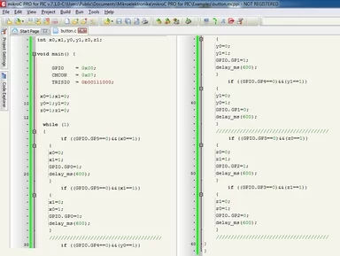
int x0,x1,y0,y1,z0,z1; ////// with this the GPIO outputs could stay on or off
void main() {
GPIO = 0x00; ////// all outputs are 0
CMCON = 0x07; ////// Disable CMCON PORT
TRISIO = 0b00111000; ////// inputs-outputs setup, 0=output 1=input (3 outputs/3 inputs)
x0=1;x1=0; ////// when the PIC starts x0=1,x1=0
y0=1;y1=0; ////// when the PIC starts y0=1,y1=0
z0=1;z1=0; ////// when the PIC starts z0=1,z1=0

while (1)
{
if ((GPIO.GP5==0)&&(x0==1)) ////// if the GPIO.GP5 grounded (pressed button) and the same time x0=1 (from the
begining of program, you see this at the previous step)
This will happen
{
x0=0; ////// the x0=1 it will be 0
x1=1; ////// the x1=0 it will be 1
GPIO.GP0=1; ////// turn the led on ( the – of the led is connected to the Ground and the + at GP0, pin 7 ) . delay_ms(600);
}
if ((GPIO.GP5==0)&&(x1==1)) ////// if the GPIO.GP5 grounded again and x1=1(from previous pressed button)
This will happen
{
x1=0; ////// x1=1 go back to 0
x0=1; ////// x0=0 go back to 1
GPIO.GP0=0; ////// now the led is off and the program wait for ((GPIO.GP5==0)&&(x0==1)) to turn on again .
delay_ms(600);
}
———————————————————-
This is for the one button and led. You have two more. See the .txt file.
Attachments
Step 3: Connection Diagram

you can use this at many projects as Latching Relay..
turn on and off circuits or devices with relay or not.
Source: Simple 3 Button On-off With 12f629 (mikroC)
- How does the code initialize the GPIO outputs?
The code sets all outputs to 0 initially with GPIO = 0x00 and disables the comparator port with CMCON = 0x07. - What is the function of the TRISIO register in this project?
TRISIO = 0b00111000 configures the pins where 0 represents an output and 1 represents an input for three inputs and three outputs. - Can the PIC12F629 be used as a latching relay controller?
Yes, the article states you can use this method for many projects as a Latching Relay to turn on and off circuits or devices. - Which pin connects to the positive side of the LED?
The positive side of the LED is connected to GP0 (pin 7), while the negative side connects to Ground. - How does the program detect a button press?
The program detects a press when GPIO.GP5 is grounded (value 0) while checking specific variable states like x0 or x1. - What happens after the LED turns on in the first condition?
The variable x0 becomes 0, x1 becomes 1, and the LED at GP0 turns on followed by a 600ms delay. - Does the LED stay on after the button is released?
Yes, the logic toggles internal variables so the LED remains on until the button is pressed again to trigger the second condition. - Is there a delay included in the button logic?
A delay of 600 milliseconds is added after turning the LED on or off to debounce the signal.