Summary of How to interface GSM Module with PIC18F4550 Microcontroller- (Part 17/25)
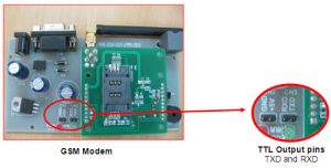
This project demonstrates interfacing a GSM module with a PIC18F4550 microcontroller to perform four key operations using AT commands: testing simple commands, retrieving the GSM modem's IMEI number, dialing a mobile number, and sending text messages. Instead of using a MAX232 line converter, the PIC18F4550 directly communicates with the GSM modem using TTL logic. Four tactile switches activate these functions, and an LCD displays results. The microcontroller communicates via USART at 9600 bps, processes inputs to send appropriate AT commands, and handles received data via interrupt for display.
Parts used in the GSM Module Interfacing with PIC18F4550 Project:
- GSM Module (supports TTL logic)
- PIC18F4550 Microcontroller
- 16x2 LCD Display
- Tactile Switches (4 units)
- Power Supply (suitable for GSM module and PIC)
- Connecting wires and PCB or breadboard
Objectives:
This project has following objectives which are fulfilled using AT Commands:
Project Source Code
###
//Program to interface GSM Modem with PIC18F4550 Microcontroller
//This code takes four choices as four inputs
//Choice 1 : Test the simple AT Command.
//Choice 2 : Find out the IMEI number of the GSM Modem.
//Choice 3 : Connect a call to a GSM mobile number.
//Choice 4 : Send a text message to a mobile number.
#define FREQ 12000000
#define baud 9600
#define spbrg_value (((FREQ/64)/baud)-1)
#define rs LATA.F0
#define rw LATA.F1
#define en LATA.F2
#define lcdport LATB
void tx_data(unsigned char);
unsigned char rx_data();
void lcd_ini();
void lcdcmd(unsigned char);
void lcddata(unsigned char);
void gsm_cmd(unsigned char *);
void output(void);
unsigned char value=0;
int i=0,j,k,temp,flag,choice;
unsigned char *starting_text=”Enter choice=”;
unsigned char *dial_text=”Dialing…”;
unsigned char *at_cmd=”AT”;
unsigned char *imei_cmd=”AT+GSN”;
unsigned char *call_cmd=”ATD9xxxxxxxxx;”; // Provide a 10-Digit Mobile Number
unsigned char *sms_format=”AT+CMGF=1″;
unsigned char *sms_write=”AT+CMGS=”xxxxxxxxxx””; // 10-Digit Mobile Number
unsigned char *sms=”Hello”;
unsigned char *sms_report=”SMS Sent…”;
unsigned char sms_terminate=0x1A;
unsigned char enter=0x0D;
unsigned char *data;
void main()
{
TRISB=0; // Set Port B as output port
LATB=0;
TRISA=0;
LATA=0;
TRISD=0xFF;
LATD=0;
SPBRG=spbrg_value; // Fill SPBRG register to set the baud rate
RCSTA.SPEN=1; // To activate serial port (Tx and Rx pins)
TXSTA.TXEN=1; // Activate Transmissiom
RCSTA.CREN=1; // Activate Reception
PIE1.RCIE=1; // Enable Reception interrupt
INTCON.GIE=1; // Enable Global interrupt
INTCON.PEIE=1; // Enable Peripheral interrupt
lcd_ini();
while(1)
{
k=0;
lcdcmd(0x80);
while(starting_text[k]!=”)
{
lcddata(starting_text[k]);
k++;
}
//Check inputs
//Choice 1
if(PORTD.F0)
{
gsm_cmd(at_cmd);
output();
Delay_ms(1000);
}
//Choice 2
if(PORTD.F1)
{
gsm_cmd(imei_cmd);
output();
Delay_ms(1000);
}
//Choice 3
if(PORTD.F2)
{
gsm_cmd(call_cmd);
output();
Delay_ms(1000);
}
//Choice 4
if(PORTD.F3)
{
gsm_cmd(sms_format);
output();
Delay_ms(1000);
gsm_cmd(sms_write);
output();
Delay_ms(1000);
gsm_cmd(sms);
output();
tx_data(0x1A);
Delay_ms(1000);
}
}
}
void gsm_cmd(unsigned char *string)
{
i=0;j=0;
while(string[i]!=”)
{
temp=0;
if(string[i]==0x5C) // Not to send ” cahracter
i++;
tx_data(string[i]); // Send by serial communication
i++;
while(temp!=1);
}
temp=0;
tx_data(enter); // Send ASCII code for ‘Enter’ key
while(temp!=1);
}
void output(void) // To print data on LCD
{
lcdcmd(0x01);
i=-1;flag=0;
while(i<j)
{
if(flag>1)
{
flag=0;
Delay_ms(500);
lcdcmd(0x01);
lcdcmd(0x80);
}
if(data[i]==0x0A) // This condition is to avoid double Enter
// during execution of a command
{
flag++;
lcdcmd(0xc0);
}
if(data[i]==’>’||data[i]=='”‘) // Not to print this character
{
i++;
lcdcmd(0xc0);
}
if(data[i]!=0x0D&&data[i]!=0x0A&&data[i]!=0x1A) // Condition to print the data
// except ‘Enter’,’New line’ and ‘Submit’
{
lcddata(data[i]);
i++;
}
else
i++;
Delay_ms(300);
}
lcdcmd(0x01);
}
void tx_data(unsigned char serial_data) // Transmit data function
{
TXREG=serial_data;
while(PIR1.TXIF==0);
}
void interrupt()
{
data[j]=RCREG; // Store the data into array when Reception interrupt occurs
value=RCREG;
j++;
temp=1;
}
void lcd_ini()
{
lcdcmd(0x38); // Configure the LCD in 8-bit mode, 2 line and 5×7 font
lcdcmd(0x0C); // Display On and Cursor Off
lcdcmd(0x01); // Clear display screen
lcdcmd(0x06); // Increment cursor
lcdcmd(0x80); // Set cursor position to 1st line, 1st column
}
void lcdcmd(unsigned char cmdout)
{
lcdport=cmdout; //Send command to lcdport=PORTB
rs=0;
rw=0;
en=1;
Delay_ms(10);
en=0;
}
void lcddata(unsigned char dataout)
{
lcdport=dataout; //Send data to lcdport=PORTB
rs=1;
rw=0;
en=1;
Delay_ms(10);
en=0;
}
###
Source: How to interface GSM Module with PIC18F4550 Microcontroller- (Part 17/25)