
Summary of Interfacing Fingerprint Sensor with PIC Microcontroller
This article details a project interfacing a fingerprint sensor with a PIC16F877A microcontroller to create an identity verification system. The setup allows users to enroll new fingerprints, match existing ones, and delete stored entries via a 16x2 LCD and push buttons. Communication between the sensor and microcontroller occurs over UART at 57600 baud. The system uses specific frame formats defined in the R305 module datasheet for command transmission and data reception, controlled by C code uploaded to the chip.
Parts used in the PIC Microcontroller Fingerprint System:
- PIC16f877A Microcontroller
- Fingerprint Module
- Push buttons or keypad
- 16x2 LCD
- 10k pot
- 18.432000 MHz Crystal Oscillator
- Bread Board or PCB
- Jumper wires
- LED (optional)
- Resistor 150 ohm -1 k ohm (optional)
- 5v Power supply
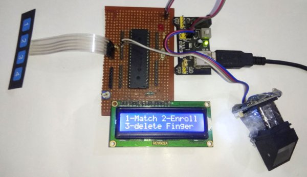
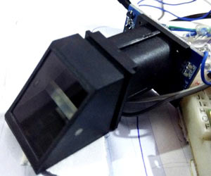
Finger Print Sensor, which we used to see in Sci-Fi movies a few years back, is now become very common to verify the identity of a person for various purposes. In present time we can see fingerprint-based systems everywhere in our daily life like for attendance in offices, employee verification in banks, for cash withdrawal or deposits in ATMs, for identity verification in government offices etc. We have already interfaced it with Arduino and with Raspberry Pi, today we are going to interface Finger Print Sensor with PIC microcontroller. Using this PIC microcontroller PIC16f877A Finger Print System, we can enroll new fingerprints in the system and can delete the already fed fingerprints. Complete working of the system has been shown in the Video given at the end of article.
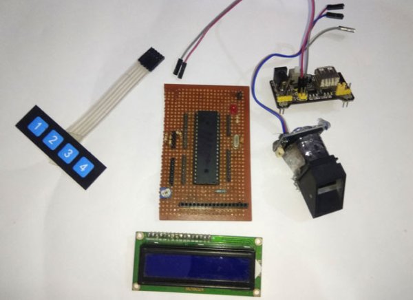
Required Components
- PIC16f877A Microcontroller
- Fingerprint Module
- Push buttons or keypad
- 16×2 LCD
- 10k pot
- 18.432000 MHz Crystal Oscillator
- Bread Board or PCB (ordered from JLCPCB)
- Jumper wires
- LED (optional)
- Resistor 150 ohm -1 k ohm (optional)
- 5v Power supply
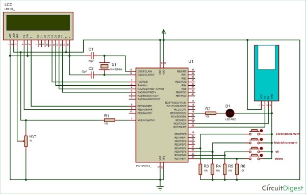
Circuit Diagram and Explanation
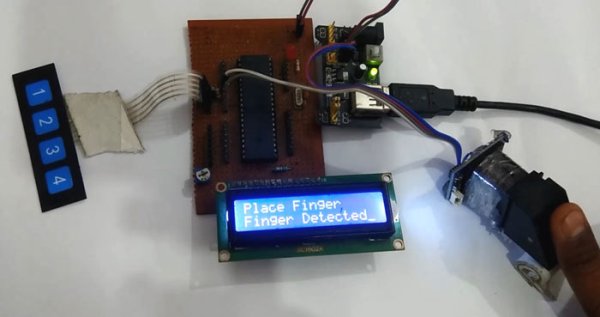
In this PIC Microcontroller Finger Print sensor interfacing project, we have used 4 push buttons: these buttons are used for multifunctioning. Key 1 is used for matching the finger print and increment fingerprint ID while storing or deleting the fingerprint in the system. Key 2 is used for enrolling the new fingerprint and for decrement fingerprint ID while storing or deleting fingerprint in the system. Key 3 is used for delete stored finger from the system and key 4 is used for OK. A LED is used for an indication that fingerprint is detected or matched. Here we have used a fingerprint module which works on UART. So here we have interfaced this fingerprint module with PIC microcontroller at its default baud rate which is 57600.
So, first of all, we need to make the all the required connection as shown in Circuit Diagram below. Connections are simple, we have just connected fingerprint module to PIC microcontroller’s UART. A 16×2 LCD is used for displaying all messages. A 10k pot is also used with LCD for controlling the contrast of the same. 16×2 LCD data pins are connected PORTA pins. LCD’s d4, d5, d6, and d7 pins are connected with Pin RA0, RA1, RA2, and RA3 of PIC microcontroller respectively. Four push buttons (or keypad) is connected to PORTD’s Pin RD0, RD1, RD2, and RD. LED is also connected at port PORTC’s pin RC3. Here we have used an 18.432000 MHz external crystal oscillator to clock the microcontroller.
Operation of Fingerprint Sensor with PIC Microcontroller
Operation of this project is simple, just upload hex file, generated from source code, into the PIC microcontroller with the help of PIC programmer or burner (PIckit2 or Pickit3 or others)and then you will see some intro messages over LCD and then the user will be asked to enter a choice for operations. To match fingerprint user need to press key 1 then LCD will ask for Place Finger on Finger Print Sensor. Now by putting a finger over fingerprint module, we can check whether our fingerprints are already stored or not. If your fingerprint is stored then LCD will show the message with the storing ID of fingerprint-like ‘ID:2’ otherwise it will show ‘Not Found’.
Now to enroll a finger Print, the user needs to press enroll button or key 2 and follow the instructions messages on the LCD screen.
If the user wants to delete any of fingerprints then the user needs to press the delete button or key 3. After which, LCD will ask for the ID of the fingerprint which is to be deleted. Now by using increment push button or key 1(match push button or key 1) and decrement push button or key 2 (enroll push button or key 2) for increment and decrement, the user can select the ID of saved Finger Print and press OK button to delete that fingerprint. For more understanding have a look at the video given at the end of the project.
FingerPrint interfacing Note: Program of this project is a little bit complex for a beginner. But its simple interfacing code made by using reading r305 fingerprint module datasheet. All the instruction of functioning of this fingerprint module is given in the datasheet.
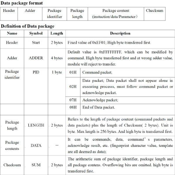
Here we have used a frame format to talk with fingerprint module. Whenever we send a command or data request frame to fingerprint module it responds us with the same frame format containing data or information related to applied command. All of the data and command frame format has been given in the user manual or in the datasheet of R305 fingerprint module.
Programming Explanation
In programming, we have used the below frame format.
We begin the program by setting the configuration bits and defining macros and pins for LCD, Buttons and LED, which you can check in the complete code given at the end of this project. If you are new to PIC Microcontroller then start with Getting started with PIC Microcontroller Project.
Then we declared and initialized some variable and array, and made a frame that we need to use in this project to interface fingerprint module with PIC microcontroller.
uchar buf[20];
uchar buf1[20];
volatile uint index=0;
volatile int flag=0;
uint msCount=0;
uint g_timerflag=1;
volatile uint count=0;
uchar data[10];
uint id=1;

enum
{
 CMD,
 DATA,
 SBIT_CREN=4,
 SBIT_TXEN,
 SBIT_SPEN,
};

const char passPack[]={0xEF, 0x1, 0xFF, 0xFF, 0xFF, 0xFF, 0x1, 0x0, 0x7, 0x13, 0x0, 0x0, 0x0, 0x0, 0x0, 0x1B};
const char f_detect[]={0xEF, 0x1, 0xFF, 0xFF, 0xFF, 0xFF, 0x1, 0x0, 0x3, 0x1, 0x0, 0x5};
const char f_imz2ch1[]={0xEF, 0x1, 0xFF, 0xFF, 0xFF, 0xFF, 0x1, 0x0, 0x4, 0x2, 0x1, 0x0, 0x8};
const char f_imz2ch2[]={0xEF, 0x1, 0xFF, 0xFF, 0xFF, 0xFF, 0x1, 0x0, 0x4, 0x2, 0x2, 0x0, 0x9};
const char f_createModel[]={0xEF,0x1,0xFF,0xFF,0xFF,0xFF,0x1,0x0,0x3,0x5,0x0,0x9};
char f_storeModel[]={0xEF,0x1,0xFF,0xFF,0xFF,0xFF,0x1,0x0,0x6,0x6,0x1,0x0,0x1,0x0,0xE};
const char f_search[]={0xEF, 0x1, 0xFF, 0xFF, 0xFF, 0xFF, 0x1, 0x0, 0x8, 0x1B, 0x1, 0x0, 0x0, 0x0, 0xA3, 0x0, 0xC8};
char f_delete[]={0xEF,0x1,0xFF,0xFF,0xFF,0xFF,0x1,0x0,0x7,0xC,0x0,0x0,0x0,0x1,0x0,0x15};
After it, we have made LCD function to drive LCD.
void lcdwrite(uchar ch,uchar rw)
{
LCDPORT= ch>>4 & 0x0F;
RS=rw;
EN=1;
__delay_ms(5);
EN=0;
LCDPORT= ch & 0x0F;
EN=1;
__delay_ms(5);
EN=0;
}
lcdprint(char *str)
{
while(*str)
{
lcdwrite(*str++,DATA);
//__delay_ms(20);
}
}
lcdbegin()
{
uchar lcdcmd[5]={0x02,0x28,0x0E,0x06,0x01};
uint i=0;
for(i=0;i<5;i++)
lcdwrite(lcdcmd[i], CMD);
}
Given function is used for initializing UART
void serialbegin(uint baudrate)
{
  SPBRG = (18432000UL/(long)(64UL*baudrate))-1;      // baud rate @18.432000Mhz Clock
    TXSTAbits.SYNC = 0;                              //Setting Asynchronous Mode, ie UART
    RCSTAbits.SPEN = 1;                              //Enables Serial Port
    TRISC7 = 1;                                   //As Prescribed in Datasheet
    TRISC6 = 0;                                   //As Prescribed in Datasheet
    RCSTAbits.CREN = 1;                                     //Enables Continuous Reception
    TXSTAbits.TXEN = 1;                                     //Enables Transmission

    GIE  = 1; // ENABLE interrupts
    INTCONbits.PEIE = 1; // ENable peripheral interrupts.
    PIE1bits.RCIE   = 1; // ENABLE USART receive interrupt
    PIE1bits.TXIE   = 0; // disable USART TX interrupt

    PIR1bits.RCIF = 0;
}
Given functions are used for transferring commands to fingerprint Module and receiving data from fingerprint module.
void serialwrite(char ch)
{
    while(TXIF==0);  // Wait till the transmitter register becomes empty
    TXIF=0;          // Clear transmitter flag
    TXREG=ch;        // load the char to be transmitted into transmit reg
}

serialprint(char *str)
{
    while(*str)
    {
        serialwrite(*str++);
    }
}

void interrupt SerialRxPinInterrupt(void)
{
    if((PIR1bits.RCIF == 1) && (PIE1bits.RCIE == 1))
    {

        uchar ch=RCREG;
        buf[index++]=ch;
        if(index>0)
            flag=1;
        RCIF = 0; // clear rx flag
    }
}

void serialFlush()
{
    for(int i=0;i<sizeof(buf);i++)
    {
        buf[i]=0;
    }
}
After it we need to make a function which prepares data that is to be transmitted to fingerprint and decode the data coming from fingerprint module.
int sendcmd2fp(char *pack, int len)
{
  uint res=ERROR;
  serialFlush();
  index=0;
  __delay_ms(100);
  for(int i=0;i<len;i++)
  {
    serialwrite(*(pack+i));
  }
  __delay_ms(1000);
  if(flag == 1)
  {
    if(buf[0] == 0xEF && buf[1] == 0x01)
    {
        if(buf[6] == 0x07)   // ack
        {
        if(buf[9] == 0)
        {
            uint data_len= buf[7];
            data_len<<=8;
            data_len|=buf[8];
            for(int i=0;i<data_len;i++)
                data[i]=0;
            for(int i=0;i<data_len-2;i++)
            {
                data[i]=buf[10+i];
            }
            res=PASS;
        }

        else
        {
         res=ERROR;
        }
        }
    }
Now, there are four function available in the code for four different task:
- Function for input the fingerprint ID – unit getId()
- Function for matching finger – void matchFinger()
- Function for enrolling new finger – void enrolFinger()
- Function for deleting a finger – void deleteFinger()
The complete code with all the four function is given at the end.
Now in the main function, we initialize GPIOs, LCD, UART and check whether the fingerprint module is connected with a microcontroller or not. Then it shows some intro messages over LCD. Finally in while loop we read all keys or push buttons to operate the project.
int main()
{
  void (*FP)();
  ADCON1=0b00000110;
  LEDdir= 0;
  SWPORTdir=0xF0;
  SWPORT=0x0F;
  serialbegin(57600);
  LCDPORTDIR=0x00;
  TRISE=0;
  lcdbegin();
  lcdprint("Fingerprint");
  lcdwrite(192,CMD);
  lcdprint("Interfacing");
  __delay_ms(2000);
  lcdwrite(1,CMD);
  lcdprint("Using PIC16F877A");
  lcdwrite(192,CMD);
  lcdprint("Circuit Digest");
  __delay_ms(2000);
  index=0;
  while(sendcmd2fp(&passPack[0],sizeof(passPack)))
  {
     lcdwrite(1,CMD);
     lcdprint("FP Not Found");
     __delay_ms(2000);
     index=0;
  }
  lcdwrite(1,CMD);
  lcdprint("FP Found");
  __delay_ms(1000);
  lcdinst();
  while(1)
  {
    FP=match<enrol?matchFinger:enrol<delet?enrolFinger:delet<enrol?deleteFinger:lcdinst;
    FP();
  }
  return 0;
}
#define _XTAL_FREQ 18432000
#include <xc.h>
#include<pic.h>
#include <stdio.h>
#include <stdlib.h>
// BEGIN CONFIG
#pragma config FOSC = HS // Oscillator Selection bits (HS oscillator)
#pragma config WDTE = OFF // Watchdog Timer Enable bit (WDT enabled)
#pragma config PWRTE = OFF // Power-up Timer Enable bit (PWRT disabled)
#pragma config BOREN = ON // Brown-out Reset Enable bit (BOR enabled)
#pragma config LVP = OFF // Low-Voltage (Single-Supply) In-Circuit Serial Programming Enable bit (RB3 is digital I/O, HV on MCLR must be used for programming)
#pragma config CPD = OFF // Data EEPROM Memory Code Protection bit (Data EEPROM code protection off)
#pragma config WRT = OFF // Flash Program Memory Write Enable bits (Write protection off; all program memory may be written to by EECON control)
#pragma config CP = OFF // Flash Program Memory Code Protection bit (Code protection off)
//END CONFIG
#define uchar unsigned char
#define uint unsigned int
#define LCDPORTDIR TRISA
#define LCDPORT PORTA
#define RS RE1
#define EN RE0
#define SWPORTdir TRISD
#define SWPORT PORTD
#define enrol RD4
#define match RD5
#define delet RD7
#define ok RD6
#define up RD5
#define down RD4
#define LEDdir TRISC3
#define LED RC3
#define HIGH 1
#define LOW 0
#define PASS 0
#define ERROR 1
#define checkKey(id) id=up<down?++id:down<up?–id:id;
uchar buf[20];
uchar buf1[20];
volatile uint index=0;
volatile int flag=0;
uint msCount=0;
uint g_timerflag=1;
volatile uint count=0;
uchar data[10];
uint id=1;
enum
{
CMD,
DATA,
SBIT_CREN=4,
SBIT_TXEN,
SBIT_SPEN,
};
const char passPack[]={0xEF, 0x1, 0xFF, 0xFF, 0xFF, 0xFF, 0x1, 0x0, 0x7, 0x13, 0x0, 0x0, 0x0, 0x0, 0x0, 0x1B};
const char f_detect[]={0xEF, 0x1, 0xFF, 0xFF, 0xFF, 0xFF, 0x1, 0x0, 0x3, 0x1, 0x0, 0x5};
const char f_imz2ch1[]={0xEF, 0x1, 0xFF, 0xFF, 0xFF, 0xFF, 0x1, 0x0, 0x4, 0x2, 0x1, 0x0, 0x8};
const char f_imz2ch2[]={0xEF, 0x1, 0xFF, 0xFF, 0xFF, 0xFF, 0x1, 0x0, 0x4, 0x2, 0x2, 0x0, 0x9};
const char f_createModel[]={0xEF,0x1,0xFF,0xFF,0xFF,0xFF,0x1,0x0,0x3,0x5,0x0,0x9};
char f_storeModel[]={0xEF,0x1,0xFF,0xFF,0xFF,0xFF,0x1,0x0,0x6,0x6,0x1,0x0,0x1,0x0,0xE};
const char f_search[]={0xEF, 0x1, 0xFF, 0xFF, 0xFF, 0xFF, 0x1, 0x0, 0x8, 0x1B, 0x1, 0x0, 0x0, 0x0, 0xA3, 0x0, 0xC8};
char f_delete[]={0xEF,0x1,0xFF,0xFF,0xFF,0xFF,0x1,0x0,0x7,0xC,0x0,0x0,0x0,0x1,0x0,0x15};
void lcdwrite(uchar ch,uchar rw)
{
LCDPORT= ch>>4 & 0x0F;
RS=rw;
EN=1;
__delay_ms(5);
EN=0;
LCDPORT= ch & 0x0F;
EN=1;
__delay_ms(5);
EN=0;
}
lcdprint(char *str)
{
while(*str)
{
lcdwrite(*str++,DATA);
//__delay_ms(20);
}
}
lcdbegin()
{
uchar lcdcmd[5]={0x02,0x28,0x0E,0x06,0x01};
uint i=0;
for(i=0;i<5;i++)
lcdwrite(lcdcmd[i], CMD);
}
void lcdinst()
{
lcdwrite(0x80, CMD);
lcdprint(“1-Match 2-Enroll”);
lcdwrite(0xc0, CMD);
lcdprint(“3-delete Finger”);
__delay_ms(10);
}
void serialbegin(uint baudrate)
{
SPBRG = (18432000UL/(long)(64UL*baudrate))-1; // baud rate @18.432000Mhz Clock
TXSTAbits.SYNC = 0; //Setting Asynchronous Mode, ie UART
RCSTAbits.SPEN = 1; //Enables Serial Port
TRISC7 = 1; //As Prescribed in Datasheet
TRISC6 = 0; //As Prescribed in Datasheet
RCSTAbits.CREN = 1; //Enables Continuous Reception
TXSTAbits.TXEN = 1; //Enables Transmission
GIE = 1; // ENABLE interrupts
INTCONbits.PEIE = 1; // ENable peripheral interrupts.
PIE1bits.RCIE = 1; // ENABLE USART receive interrupt
PIE1bits.TXIE = 0; // disable USART TX interrupt
PIR1bits.RCIF = 0;
}
void serialwrite(char ch)
{
while(TXIF==0); // Wait till the transmitter register becomes empty
TXIF=0; // Clear transmitter flag
TXREG=ch; // load the char to be transmitted into transmit reg
}
serialprint(char *str)
{
while(*str)
{
serialwrite(*str++);
}
}
void interrupt SerialRxPinInterrupt(void)
{
if((PIR1bits.RCIF == 1) && (PIE1bits.RCIE == 1))
{
uchar ch=RCREG;
buf[index++]=ch;
if(index>0)
flag=1;
RCIF = 0; // clear rx flag
}
}
void serialFlush()
{
for(int i=0;i<sizeof(buf);i++)
{
buf[i]=0;
}
}
int sendcmd2fp(char *pack, int len)
{
uint res=ERROR;
serialFlush();
index=0;
__delay_ms(100);
for(int i=0;i<len;i++)
{
serialwrite(*(pack+i));
}
__delay_ms(1000);
if(flag == 1)
{
if(buf[0] == 0xEF && buf[1] == 0x01)
{
if(buf[6] == 0x07) // ack
{
if(buf[9] == 0)
{
uint data_len= buf[7];
data_len<<=8;
data_len|=buf[8];
for(int i=0;i<data_len;i++)
data[i]=0;
for(int i=0;i<data_len-2;i++)
{
data[i]=buf[10+i];
}
res=PASS;
}
else
{
res=ERROR;
}
}
}
index=0;
flag=0;
return res;
}
}
uint getId()
{
uint id=0;
lcdwrite(1, CMD);
while(1)
{
lcdwrite(0x80, CMD);
checkKey(id);
sprintf(buf1,”Enter Id:%d “,id);
lcdprint(buf1);
__delay_ms(200);
if(ok == LOW)
return id;
}
}
void matchFinger()
{
lcdwrite(1,CMD);
lcdprint(“Place Finger”);
lcdwrite(192,CMD);
__delay_ms(2000);
if(!sendcmd2fp(&f_detect[0],sizeof(f_detect)))
{
if(!sendcmd2fp(&f_imz2ch1[0],sizeof(f_imz2ch1)))
{
if(!sendcmd2fp(&f_search[0],sizeof(f_search)))
{
lcdwrite(1,CMD);
lcdprint(“Finger Found”);
uint id= data[0];
id<<=8;
id+=data[1];
uint score=data[2];
score<<=8;
score+=data[3];
sprintf(buf1,”Id:%d Score:%d”,id,score);
lcdwrite(192,CMD);
lcdprint(buf1);
LED=1;
__delay_ms(1000);
LED=0;
}
else
{
lcdwrite(1,CMD);
lcdprint(“Not Found”);
}
}
}
else
{
lcdprint(“No Finger”);
}
__delay_ms(2000);
}
void enrolFinger()
{
lcdwrite(1,CMD);
lcdprint(“Enroll Finger”);
__delay_ms(2000);
lcdwrite(1,CMD);
lcdprint(“Place Finger”);
lcdwrite(192,CMD);
__delay_ms(1000);
if(!sendcmd2fp(&f_detect[0],sizeof(f_detect)))
{
if(!sendcmd2fp(&f_imz2ch1[0],sizeof(f_imz2ch1)))
{
lcdprint(“Finger Detected”);
__delay_ms(1000);
lcdwrite(1,CMD);
lcdprint(“Place Finger”);
lcdwrite(192,CMD);
lcdprint(” Again “);
__delay_ms(2000);
if(!sendcmd2fp(&f_detect[0],sizeof(f_detect)))
{
if(!sendcmd2fp(&f_imz2ch2[0],sizeof(f_imz2ch2)))
{
lcdwrite(1,CMD);
lcdprint(“Finger Detected”);
__delay_ms(1000);
if(!sendcmd2fp(&f_createModel[0],sizeof(f_createModel)))
{
id=getId();
f_storeModel[11]= (id>>8) & 0xff;
f_storeModel[12]= id & 0xff;
f_storeModel[14]= 14+id;
if(!sendcmd2fp(&f_storeModel[0],sizeof(f_storeModel)))
{
lcdwrite(1,CMD);
lcdprint(“Finger Stored”);
sprintf(buf1,”Id:%d”,id);
lcdwrite(192,CMD);
lcdprint(buf1);
__delay_ms(1000);
}
else
{
lcdwrite(1,CMD);
lcdprint(“Finger Not Stored”);
}
}
else
lcdprint(“Error”);
}
else
lcdprint(“Error”);
}
else
lcdprint(“No Finger”);
}
}
else
{
lcdprint(“No Finger”);
}
__delay_ms(2000);
}
void deleteFinger()
{
id=getId();
f_delete[10]=id>>8 & 0xff;
f_delete[11]=id & 0xff;
f_delete[14]=(21+id)>>8 & 0xff;
f_delete[15]=(21+id) & 0xff;
if(!sendcmd2fp(&f_delete[0],sizeof(f_delete)))
{
lcdwrite(1,CMD);
sprintf(buf1,”Finger ID %d “,id);
lcdprint(buf1);
lcdwrite(192, CMD);
lcdprint(“Deleted Success”);
}
else
{
lcdwrite(1,CMD);
lcdprint(“Error”);
}
__delay_ms(2000);
}
int main()
{
void (*FP)();
ADCON1=0b00000110;
LEDdir= 0;
SWPORTdir=0xF0;
SWPORT=0x0F;
serialbegin(57600);
LCDPORTDIR=0x00;
TRISE=0;
lcdbegin();
lcdprint(“Fingerprint”);
lcdwrite(192,CMD);
lcdprint(“Interfacing”);
__delay_ms(2000);
lcdwrite(1,CMD);
lcdprint(“Using PIC16F877A”);
lcdwrite(192,CMD);
lcdprint(“Circuit Digest”);
__delay_ms(2000);
index=0;
while(sendcmd2fp(&passPack[0],sizeof(passPack)))
{
lcdwrite(1,CMD);
lcdprint(“FP Not Found”);
__delay_ms(2000);
index=0;
}
lcdwrite(1,CMD);
lcdprint(“FP Found”);
__delay_ms(1000);
lcdinst();
while(1)
{
FP=match<enrol?matchFinger:enrol<delet?enrolFinger:delet<enrol?deleteFinger:lcdinst;
FP();
}
return 0;
}
Source :Interfacing Fingerprint Sensor with PIC Microcontroller
- How do I match a fingerprint using this system?
Press Key 1, then place your finger on the sensor; the LCD will display the ID if found or Not Found. - Can I enroll a new fingerprint into the system?
Yes, press Key 2, follow the LCD instructions to place your finger twice, enter an ID, and press OK. - Does the system allow deleting stored fingerprints?
Yes, press Key 3, select the ID using increment/decrement keys, and press OK to delete it. - What is the default baud rate for the fingerprint module?
The module operates at a default baud rate of 57600. - Which pins connect the LCD data lines to the microcontroller?
LCD data pins d4 through d7 connect to PORTA pins RA0, RA1, RA2, and RA3 respectively. - What component controls the contrast of the LCD?
A 10k potentiometer is connected to the LCD to control its contrast. - How does the LED indicate status?
The LED lights up when a fingerprint is detected or matched successfully. - What clock frequency is required for the microcontroller?
An 18.432000 MHz external crystal oscillator is used to clock the microcontroller. - Where can I find the complete source code?
The complete code is provided at the end of the article text.
