Battery monitor on a automotive realy form factor
Hi all! I’m really busy this year so I can’t post all the projects where I’m involved. Here’s one of the design I do last year for a client. He wants to measure the voltage of a car battery and set a couple of alarms when voltage falls below a defined values. Also, he wants to put the device in the relay box of the car, so the design needs to have a relay form factor to easy integration. So, after a couple of iterations, here’s the final design of the battery monitor.
The project start around a year ago. The client wants a device to integrate in the relay box of some vehicles to monitor the voltage of the battery (12V nominal value). He wants two alarms at two different voltages. The alarm output will activate other external relays for advertising the low level of the battery, so I use a couple of small SSR for this outputs. Also he wants to configure the time to enable / disable alarms: once the device detect a voltage lower or higher than configurated values, the device needs to wait some time (configurable) before actívate or desactivate the alarms.
- PROTOTYPES
Here’s the first proof of concept, with components I’ve got at home and one afternoon of work;
Mains components of this board are:
- PTN78000WAH: 1.5-A wide input adjustable switching regulator, to obtain 5V from 12V input. Obviously oversized and cost – prohibited for this design.
- PIC16F88: A small 8-bit microcontroller from Microchip, to implement all the logic. Expensive and old device but it allows me start with the code. For this I use the mikroC PRO for PIC compiler and the mikroProg programmer, both from mikroe company. On my previous post I cover how to make compatible this programmer with the PicKit 3 programmer from Microchip.
- AQZ205: Solid-State relay. AC/DC dual use, with 100V load voltage and 4 amps load current. Again oversized but perfect for the demo, allowing the client to connect a external relay without problems to activate it. To test the board, I only put one SSR on it.
- To measure the battery voltage, I use a simple network divider with a low pass filter and internal ADC of the PIC16F88.
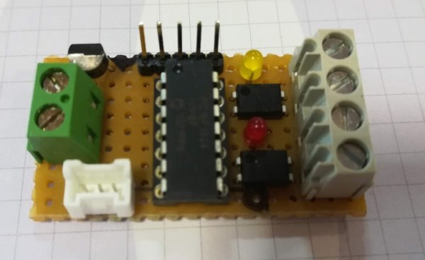
After some test with the client, he gives me the OK to go on. Proof of concept was fine but now I need to adjust all the components as much as I can to have a device with adjusted costs. I make a new prototype with the new components (and the two SSR relays):
Read more: Vehicle Battery monitor on a automotive relay form factor