Summary of Simple nanosecond-width pulse generator provides high performance
The article describes a predictably programmable short-time-interval pulse generator that produces 0–10 ns output pulses with ~520 ps, 5V transitions and ±100 ps pulse-width stability over 65% supply variation. Built with a quad high-speed comparator and a high-speed gate, the design uses RC networks and a programming resistor to set pulse width; typical performance includes minimum trigger width 30 ns, 18 ns input-output delay, and measured pulses down to 1 ns (full amplitude) or 700 ps (partial amplitude).
Parts used in the Predictably Programmable Short-Time-Interval Generator:
- Quad high-speed comparator (IC1–IC3)
- High-speed gate (G1)
- Programming resistor RG
- Fixed RC network
- Variable RC network
- 50 Ω termination
- Coaxial probe/cabling for measurement
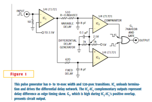
If you need to produce extremely fast pulses in response to an input and trigger, such as for sampling applications, the predictably programmable short-time-interval generator has broad uses. The circuit of Figure 1, built around a quad high-speed comparator and a high-speed gate, has settable 0- to 10 ns output width with 520 ps, 5V transitions. Pulse width varies less than 100 ps with 5V supply variations of 65%. The minimum input-trigger width is 30 ns, and input-output delay is 18 ns.
Comparator IC1 inverts the input pulse (Figure 2, Trace A) and isolates the 50Ω termination. IC1‘s output drives fixed and variable RC networks. Programming resistor RG primarily determines the networks’ charge-time difference and, hence, delay at a scale factor of approx 80Ω/ns. Comparators IC2 and IC3, arranged as complementary-output-level detectors, represent the networks’ delay difference as edge-timing skew. Trace B is IC3‘s fixed-path output, and Trace C is IC2‘s variable output. Gate G1‘s output (Trace D), which is high during IC2-IC3 positive overlap, presents the circuit output pulse. Figure 2 shows a 5V, 5ns width, measured at 50% amplitude, output pulse with R=390Ω. The pulse is clean and has well-defined transitions. Post-transition aberrations, within 8%, derive from G1‘s bond-wire inductance and an imperfect coaxial probing path. Figure 3 shows the narrowest full amplitude, 5V pulse available. Width measures 1ns at the 50% amplitude point and 1.7 ns at the base in a 3.9 GHz bandwidth. Shorter widths are available if partial amplitude pulses are acceptable. Figure 4 shows a 3.3V, 700 ps width (50%) with a 1.25 ns base. G1‘s rise time limits minimum achievable pulse width. The partial-amplitude pulse, 3.3V high, measures 700 ps with a 1.25 ns base (Figure 5). Figure 6, taken in a 3.9 GHz sampled bandpass, measures 520 ps rise time. Fall time is similar. The transition of the probe edge is well-defined and free of artifacts.
For More Details: Simple nanosecond-width pulse generator provides high performance
- What pulse widths can this generator produce?
The generator produces 0 to 10 ns selectable output width, with measured full-amplitude pulses down to 1 ns (50%) and partial-amplitude pulses down to 700 ps (50%). - What transition times does the circuit achieve?
Measured rise time is about 520 ps at 5 V amplitude in a 3.9 GHz sampled bandwidth; fall time is similar. - How stable is the pulse width with supply variation?
Pulse width varies less than 100 ps with a 65% change in the 5 V supply. - What components determine the pulse width?
Pulse width is set by fixed and variable RC networks, with programming resistor RG primarily determining charge-time difference and delay. - What is the minimum input-trigger width?
The minimum input-trigger width specified is 30 ns. - What is the input to output delay?
Input-output delay of the circuit is 18 ns. - What limits the minimum achievable pulse width?
G1's rise time (the high-speed gate) limits the minimum achievable pulse width. - How is the output pulse formed?
Comparators IC2 and IC3 detect delay difference as edge timing; gate G1 outputs a pulse when IC2 and IC3 outputs overlap positively. - What measurement bandwidth was used for rise-time figures?
Rise-time measurement of 520 ps was taken in a 3.9 GHz sampled bandpass. - Are post-transition artifacts present?
Post-transition aberrations within about 8% were observed, attributed to G1 bond-wire inductance and imperfect coaxial probing.