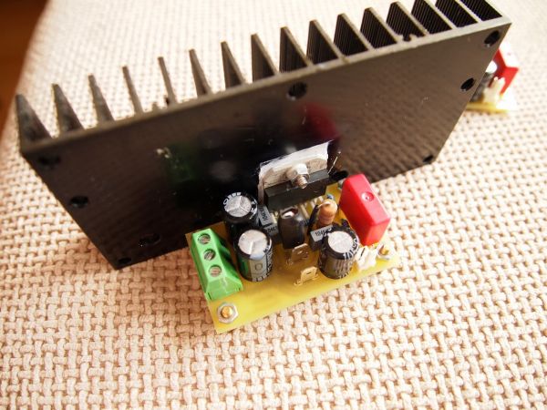
Description
This is my second encounter with LM3886. I was pleased of the sound this chip produced the first time, so I decided to make another amplifier with it. The schematic is based on the schematic in the datasheet of the chip with minor changes.
I removed the time delay capacitor connected to MUTE pin, because it’s better to use separate DC protection schematic which has similar functionality. I made the output inductance L1 by winding 15 turns of enameled wire around the resistor R7. The diameter of the wire must be minimum 0.4mm. The whole was wrapped with heat shrink. I used 47uF/63V non polarized capacitor for C2. It can be regular electrolytic capacitor, but it’s better to use non-polarized or bipolar.
The transformer is 2x24VAC / 105W. The test was ran with 8Ohm dummy load and the big heat sink gets only warm after hours of playing music from my computer at max volume. The transformer is a little weak for this amplifier, maybe 150W or 200W would be a better choice.
The power supply is very simple – a bridge rectifier and 4 x 10 000uF/50V capacitors. If the input is disconnected and open there is a little hum which can be heard only with an ear pressed against the speaker. But once the amplifier is connected via cable to the source and there is no signal, it becomes absolutely silent. Also if the heat sink is isolated from the metal tabs of the chips with some mica pads then the heat sink is good to be connected to the ground as it induces more hum in the open inputs.
It can be mounted without isolation pads for better thermal conductance, but then the heat sink itself must be isolated from the metal enclosure which usually is connected to the ground. How does it sound? Excellent 🙂
For more detail: 50W Power Amplifier with LM3886

