Summary of 433.92 MHZ RF RELAY CONTROL CIRCUIT PIC16F84
This article describes a 433.92 MHz RF relay control circuit project utilizing PIC16F84 microcontrollers. The system employs TWS-BS3 transmitters and RWS-371-6 receivers to manage relays on a 12V board. The project includes Proteus ISIS/Ares drawings and PICBasic Pro source code, contributed by forum member @erhan27 for educational and implementation purposes.
Parts used in the RF Relay Control Circuit:
- TWS-BS3 433.92 MHz RF transmitter module
- RWS-371-6 433.92 MHz RF receiver module
- PIC16F84 microcontroller
- Relay control circuit board
- 12V telekom substrate
- PICBasic Pro source code
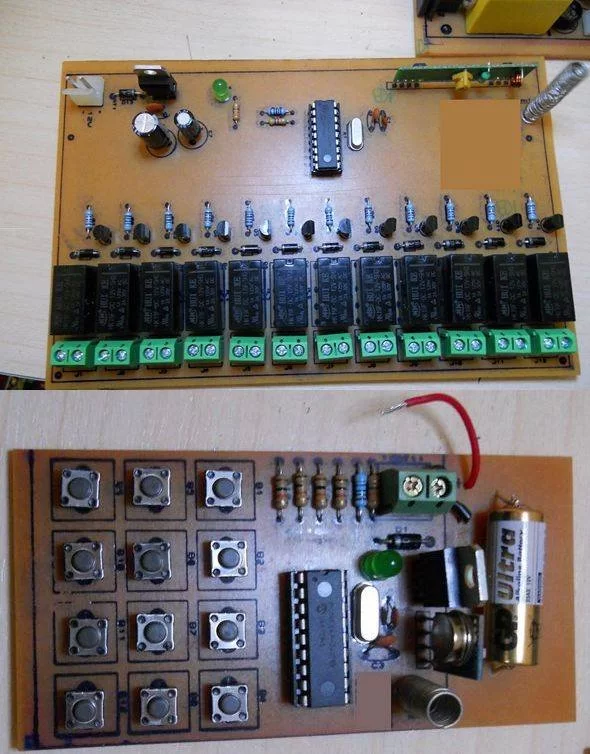
RF relay control circuit of the TWS-BS3 433.92 MHz rf transmitter and RWS-371-6 433.92 MHz rf receiver modules are used. RF relay control circuit of the receiver is used in all of the relays… Electronics Projects,433.92 MHz RF relay control circuit PIC16F84 “microchip projects, microcontroller projects, pic16f84 projects, picbasic pro examples, “
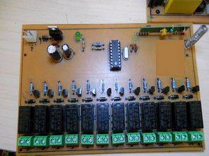
RF relay control circuit of the TWS-BS3 433.92 MHz rf transmitter and RWS-371-6 433.92 MHz rf receiver modules are used. RF relay control circuit of the receiver is used in all of the relays on the Board of the RF remote control with 12v telekom substrate pic16f84 project proteus isis, ares drawings and have the source codes for the picbasic.
Make the circuit running and sharing forum member @erhan27 thanks for sharing.
Source: 433.92 MHZ RF RELAY CONTROL CIRCUIT PIC16F84 alternative link: 433-92-mhz-rf-relay-control-circuit-pic16f84.rar
- What modules are used for the 433.92 MHz transmission?
The project uses the TWS-BS3 RF transmitter and RWS-371-6 RF receiver modules. - Which microcontroller is utilized in this design?
The PIC16F84 microcontroller is used to control the circuit. - Can I access the source code for this project?
Yes, the project includes source codes written in PICBasic Pro. - What software tools were used for the circuit drawings?
Proteus ISIS and Ares were used to create the circuit drawings. - How is the power supply configured for the board?
The board utilizes a 12V telekom substrate for power. - Who shared the working circuit details?
Forum member @erhan27 shared the circuit that makes it run. - Is there an alternative link available for the files?
An alternative link named 433-92-mhz-rf-relay-control-circuit-pic16f84.rar is provided. - What type of components control the relays?
An RF relay control circuit of the receiver is used for all relays on the board.