Summary of 4-CHANNEL RF TRANSCEIVER CIRCUIT WITH PIC16F628 APPLICATION
This article describes a 4-channel RF transceiver circuit designed to consolidate transmitter and receiver operations using the PIC16F628 microcontroller. The system operates smoothly up to 150 meters in open spaces and 50 meters indoors. It features hardware expandability for additional channels, utilizes software-based pull-up resistors via OPTION_REG commands, and includes Proteus simulation files alongside PicBasic Pro code for implementation.
Parts used in the 4-Channel RF Transceiver Circuit:
- PIC16F628 microcontroller
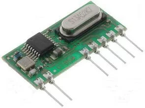
- Hybrid transmitter module
- Hybrid receiver module
- 4-way dip switch
- 4 LEDs
- Pull-up resistors (software configured)
The aim of the application circuit to consolidate the operation of the transmitter and receiver circuits. Our circuit consists of two separate circuit. 1st half 2nd half transmitter receiver circuit. The transmitter circuit 16F628, hibirit transmitter, 4-way dip switch…. Electronics Projects, 4-Channel RF Transceiver Circuit with PIC16F628 Application “microchip projects, microcontroller projects, pic16f628 projects, picbasic pro examples,
The aim of the application circuit to consolidate the operation of the transmitter and receiver circuits. Our circuit consists of two separate circuit. 1st half 2nd half transmitter receiver circuit. The transmitter circuit 16F628, hibirit transmitter, 4-way dip switch. Receiver circuit 16F628, buyers of hybrid, 4 led.devre our 4 channel RF transmitter and receiver circuit. The number of channels can be increased by hardware and software.
In 150 meters in open space are working smoothly. 50 meters closed area is working smoothly.
The transmitter circuit pull-up resistor for the switch would have to use. 16F628 own pull-up resistances are used in the software. OPTION_REG = 7 Commands we must not add to the program.
RF TRANSCEIVER CIRCUIT TEST
RF TRANSCEIVER PROTEUS ISIS SCHEMATIC
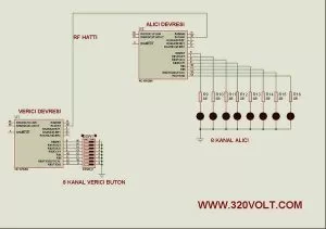
4 channel RF applications of sensor data with PIC16F628 picbasic pro code files and isis proteus simulation files:
FILE DOWNLOAD LINK LIST (in TXT format): LINKS-10229.zip
Source: 4-CHANNEL RF TRANSCEIVER CIRCUIT WITH PIC16F628 APPLICATION
- What is the main aim of this application circuit?
To consolidate the operation of the transmitter and receiver circuits. - How far can the circuit operate in an open space?
The circuit works smoothly up to 150 meters in open space. - Can the number of channels be increased?
Yes, the number of channels can be increased by modifying both hardware and software. - Does the circuit use internal pull-up resistances?
Yes, the 16F628 own pull-up resistances are used in the software. - What command must not be added to the program regarding pull-ups?
The OPTION_REG = 7 command must not be added to the program. - What simulation file is provided for this project?
A Proteus ISIS schematic file is provided for testing. - Which programming language examples are included?
PicBasic Pro code files are included with the project. - How does the closed area performance compare to open space?
It works smoothly up to 50 meters in a closed area.