Summary of 4 CHANNEL OPTO-ISOLATED MODULE USING HIGH SPEED 6N137 OPTOCOUPLER
4 Channel Opto isolated board built with 6N137 optocouplers provides high-speed digital isolation between inputs and outputs for interfacing microprocessors, line receivers, floating supplies, motors, and control systems. Each channel uses a GaAsP LED input and integrated photodiode + amplifier with Schottky-clamped open-collector output, switching low with 5 mA input and offering 13 mA on-state drive. Board runs from 5 V DC, accepts 5 V TTL inputs (with resistor changes for 3.3 V), and includes header connectors and a power LED.
Parts used in the 4 Channel Opto Isolated Board:
- 6N137 optocoupler (x4)
- Resistors R1, R4, R7, R10 (220 ohm for 3.3V inputs; otherwise unspecified for 5V)
- Power supply header (5V DC)
- Input header connectors (TTL inputs)
- Output header connectors (open-collector outputs)
- Power indicator LED (D1)
- Schottky clamp components integrated in 6N137
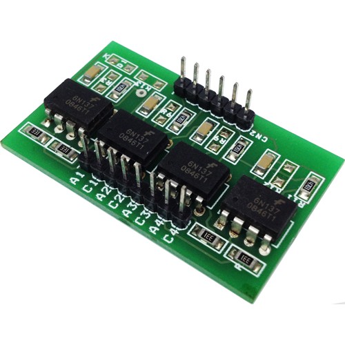
4 Channel Opto isolated board has been designed around 6N137 Opto-coupler, the 6N137 optocoupler is designed for use in high-speed digital interfacing applications that require high-voltage isolation between the input and output. Applications include line receivers, microprocessors or computer interface, digital programming of floating power supplies, motors, and other control systems.
The 6N137 high-speed optocoupler consists of a GaAsP light-emitting diode and an integrated light detector composed of a photodiode, a high-gain amplifier, and a Schottky-clamped open-collector output transistor. An input diode forward current of 5 milliamperes will switch the output transistor low, providing an on-state drive current of 13 milliamperes (eight 1.6-milliampere TTL loads).
Note : For 3.3 Input Signal R1, R4, R7, R10 = 220E
Features
- Supply 5V DC
- Input Signal : 5V DC TTL
- Header Connectors for Inputs & Outputs
- D1 Power LED
- What optocoupler is used in the project?
The project uses the 6N137 optocoupler. - What supply voltage does the board require?
The board requires a 5V DC supply. - What input signal levels does the board accept?
The board accepts 5V DC TTL input signals; for 3.3V inputs change R1, R4, R7, R10 to 220 ohm. - How much input current switches the output transistor low?
An input diode forward current of 5 milliamperes will switch the output transistor low. - What is the on-state drive current provided by the output?
The output provides an on-state drive current of 13 milliamperes. - Which components are provided for connecting signals?
The board provides header connectors for inputs and outputs. - Is there a power indicator on the board?
Yes, there is a power LED labeled D1. - What internal parts does the 6N137 include?
The 6N137 includes a GaAsP LED, a photodiode, a high-gain amplifier, and a Schottky-clamped open-collector output transistor.