Summary of 3-Channel IR Relay Controller with user programmable IR commands for PIC12F629
This article describes a 3-channel IR remote-controlled relay driver using a PIC12F629 microcontroller. It supports Sony's 12-bit SIRC protocol, allowing users to program commands and configure relays as toggle or momentary switches. The circuit uses a 12V supply, a 78L05 regulator for 5V logic, a TSOP4838 IR receiver, and NPN transistors to drive three relays with status LEDs.
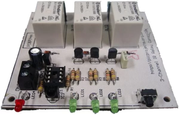
Parts used in the 3-Channel IR Relay Controller:
- PIC12F629 microcontroller
- TSOP4838 IR receiver IC
- 78L05 voltage regulator
- Diode D5
- Capacitors C2 and C3
- NPN transistors Q1, Q2, and Q3 (BC547)
- Relay coils
- Status LED (LED 4)
- Switch S1
- 470ohm resistors
- 10K resistor
Description
This project is a 3 channel infrared (IR) remote controlled relay driver. It works with 12-bit SIRC IR signals as used by Sony remote controls.
The controller also features the ability for the user to ‘program’ the commands it will respond to using the IR remote control. Each of the three relay channels can also be individually configured for either toggle or momentary switch action.
Although this project has been designed around the control of three relays, the PIC microcontroller can be incorporated in to any application where up to three logic level outputs are required to be remotely controlled.
The controller uses Microchip’s low cost PIC12F629 microcontroller along with a handful of
easy to find components making it cheap and easy to construct. Everything you need to know to build this project, including the firmware code is right here on the project page. If you don’t have access to a PIC programmer you can buy the PIC chip pre-programmed from the online-store
Don’t forget to check out the accompanying mini IR remote control which can be used with this project.
Circuit Description
The board is powered from a 12 volt DC supply input. This is fed through diode D5 which provides protection from a reversed connection of the power supply. Capacitor C2/C3 filter / decouple the 12 volt supply. The 12 volt input is fed to a 78L05 voltage regulator to provide the 5 volt supply required for the PIC microcontroller IC1 and the IR receiver IC3.
The IR signal is detected and demodulated by IC3 a TSOP4838 IR receiver IC. This part was chosen because it has a low supply current requirement – typically around 1.5mA. The output from the detector is fed to the GP2 input of microcontroller IC1. When a signal is received by the TSOP4838 it pulls the GP2 input on the PIC low, when no signal is received it is pulled high by an internal pull-up resistor. The firmware programmed into the PIC12F629, IC1 decodes the signal using the 12-bit SIRC protocol (see download section).
n.b. The circuit and code will work without modification using either a PIC12F629 or PIC12F675
The relays are switched on by microcontroller IC1 via driver transistors Q1, Q2 and Q3. These are low power NPN transistors, in this case BC547 but virtually any small NPN transistor will work here as they only need to switch around 30mA – BC548 or BC549 would also work well. The relay status LEDs are connected in series with the base of the relay drive transistor. When one of the outputs of IC1 goes high, around 5mA passes through the respective LED and 470ohm resistor to the base of the transistor, causing both the LED and transistor to turn on and activate the relay. When the output of IC1 goes low, the 10K resistor holds the base of the transistor at 0V ensuring it turns off and the relay deactivates. The diodes across the relay coils protect the transistor from the back EMF generated by the relay coil when it is de-energised.
LED 4 is a status LED, in normal operation it indicates when an IR command is being received by flashing at 20Hz. It is also used to indicate that the controller is in setup mode. Switch S1 is used to enter and exit setup mode, details of this are covered in the User Programming section.
For more information on the SIRC infrared protocol and codes see:
- http://www.hifi-remote.com/sony/
- sonysirc.pdf

- http://www.sbprojects.com/knowledge/ir/sirc.htm
Download PCB artwork in PDF ![]()
Download PCB overlay in PDF ![]()
PCB dimensions are 80mm x 75mm approx.
Suggested hole drill sizes:
- terminal blocks and S1 metal frame drill at 1.1mm
- relays drill at 1.5mm
- U1, U3 drill at 0.85mm
- PCB mounting holes drill at 3mm
- everything else drill at 0.75mm
Component List
You can buy all the parts needed to build this project from most component suppliers world wide. In the UK you can get everything from Rapid Online and I’ve included a parts list with their part numbers below.
For more detail: 3-Channel IR Relay Controller with user programmable IR commands for PIC12F629
- What type of IR signals does this controller work with?
It works with 12-bit SIRC IR signals used by Sony remote controls. - Can the user program the commands the controller responds to?
Yes, the controller features the ability for the user to program the commands it will respond to using the IR remote control. - How are the relay channels configured?
Each of the three relay channels can be individually configured for either toggle or momentary switch action. - What voltage is required to power the board?
The board is powered from a 12 volt DC supply input. - Which component provides protection against reversed power connection?
Diode D5 provides protection from a reversed connection of the power supply. - What transistor types can be used to drive the relays?
Virtually any small NPN transistor like BC547, BC548, or BC549 will work as they only need to switch around 30mA. - Does the code work with different PIC microcontrollers?
Yes, the circuit and code will work without modification using either a PIC12F629 or PIC12F675. - What indicates that an IR command is being received?
LED 4 flashes at 20Hz in normal operation to indicate when an IR command is being received. - How do you enter setup mode on the controller?
Switch S1 is used to enter and exit setup mode.