This project uses one of the smallest chips in the PIC microcontroller range, the PIC12F629 and you can learn to program it and experience the thrill of making something yourself and see what goes into writing a program.
Even a program as simple as this one is not easy to put together and if you are starting from scratch, you will need a programmer (a “burner”) and all the data that goes with “burning” and creating a program for the micro. We use the PICkit-2 as it is the cheapest and best. It comes with USB cable and 2 CD’s containing the programs needed to “burn” the chip. You will also need NotePad2 to write your .asm program
(use Whistle.asm or Whistle.txt as a template for your program).
The PC board includes 5 pins for “In Circuit Programming” via PICkit-2 and you will be encouraged to use surface-mount components to interface the piezo diaphragm to the chip.
One of the clever parts of the circuit is the piezo is used to detect the sound and then produce the beep-beep-beep reply.
Be reminded that not all piezo diaphragms are the same. Some are very sensitive when detecting audio and others are not sensitive at all.
Ours produces an output of about 20mV to 50mV when whistling up-close, while an insensitive diaphragm will produce only a few millivolts.
The CIRCUIT
The circuit consists of two common-emitter stages with enough gain to produce a rail-to-rail signal when the piezo detects a whistle.
We are not concerned about distortion or over-driving the chip as we want a fairly square wave.
A super-alpha arrangement was tried using two transistors but it did not work at all.
It is surprising how “theory” does not always work in practice and that’s why you must try everything before settling on a result. Each stage has a gain of approx 70, making the total approx 5,000. This allows a 1mV signal from the piezo to produce a rail-to-rail waveform.
As we mentioned, the interesting feature of the circuit is the use of the piezo to detect a signal and then produce a beep. This has been done by making the piezo “float.”
It is not connected to any rail and although it is connected to pins of the chip, these can be made “inputs” and thus become high impedance.
The 4k7 on the base of the transistor allows the piezo to be driven by the chip in “bridge-mode” where the pins are alternately made high then low so that twice the supply voltage is effectively delivered across the piezo to increase its output.
Without the 4k7, the lead of the piezo would not rise above 0.6v due to the base-emitter voltage limitation.
When the piezo is required to detect a signal, one lead is connected to 0v via a pin of the chip and the other lead connects to the base via the 4k7. The pin on the chip is changed to “input” during this operation.
When the piezo is activated, the signal is also amplified through the transistors but the chip is not in detection-mode and this signal is not detected.
SURFACE-MOUNT COMPONENTS
To keep in line with miniaturisation, we have used surface-mount components. Once you start using surface-mount components, you get hooked. Through-hole components seem enormous. You will need fine tweezers to hold them in place while one end is soldered.
Always use very fine solder as you only need very little for each component and the main reason for adding extra is to take advantage of the flux to clean the connection. Always solder resistors with the value showing. Capacitors don’t have values marked on them and you cannot work out the value by the size of the component.
That’s why you have to know the value before taking them out of their “carrier.”
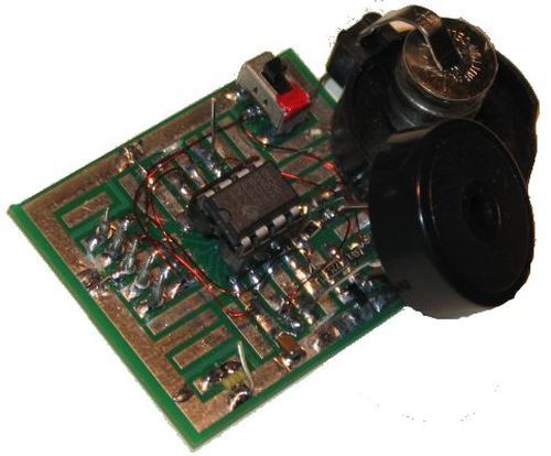
CONSTRUCTION
You can build the circuit on any type of PC board and we have used a small prototype board that needs some of the tracks cut to suit the placement of the 8 pin IC socket.
The kit of components comes with all the parts you need to get the project working, including a pre-programmed chip and a prototype PC board that needs some tracks cut.
We will not describe any construction details as most constructors will be adept in placing components. The only thing to remember is to cut the tracks before fitting the IC socket as some tracks run under the socket.
To modify the program you will need a PICkit-2 programmer and this comes with 2 CD’s containing all the software needed for In-Circuit Programming.
You will also need a lead to connect the programmer to your lap top via the USB port (comes with PICkit-2) and an adapter we call a 6pin to 5 pin Adapter to connect the PICkit-2 to your project. (The photo below shows the prototype 6pin to 5 pin Adapter. A PC board is now available for the adapter.)
For more detail: Whistle Key Finder using PIC12F629