The ‘One Chip Spinning RGB POV Display’ with conversion software.
If you have been on the look out for a project that combines, RGB LED’s, a motor, a microcontroller and a ridiculous amount of hot melt glue, then you have certainly come to the right place.
Allow me to introduce the ‘One Chip’ Spinning RGB POV Display
This project allows you to create (with minimal components) a fantastic customizable display capable of displaying graphics, animations and text. You can scroll your graphics from top to bottom or use it as a scrolling message display, scrolling from right to left.
The project uses just one chip, eight RGB LED’s and a handful of other components to paint animations in ‘mid-air!’ Plus, together with the included graphic conversion software (download link in step 2) you can easily create your own animations because the software creates all the code for you.
So please, read on and enjoy!
Step 1
Get your required parts and tools.
1x PIC 18f4680 microcontroller
1 x 40 pin IC socket (optional – to house the microcontroller)
8 x Common cathode RGB LED’s
24 x 100 ohm resistors (any wattage)
1 x 0.1 uF capacitor (optional)
2 x 100 uF capacitors
1 x 7805 (5 Volt Regulator)
2 x 10k ohm resistors
1 x hall effect sensor / hall effect switch
1 x 5 pin header (to plug in the pickit2 programmer)
1 x small rare earth magnet (to be used with the sensor)
1 x screw in type mains wiring terminator (See last photo – you get these from a hardware store)
1 x 12v motor
1 x motor (any motor that you can destroy for parts – I.E. the graphite brushes)
1 x 12v powersupply (for the motor)
1 x 7.5 volt power supply (for the POV display – can be upto about 18v)
1 x (5.5cm x 5.5cm blank pcb – aka blank copper clad) – this will be used to transfer power to the display
Holt Melt Glue Sticks
Solder
Veroboard / experimenters board
Thin enamel wire (see pic)
Standard single core wire (Like they use in network cable)Tools:
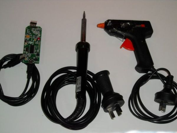
– Soldering Iron
– Screw Driver
– hot melt glue gun
– Stanley knife
– side cutters
– pliers
– pickit2 programmer
– desoldering tool (solder sucker or solder braid – just in case!)
– computer running windows
– swordfish basic compiler (this is a free download – it compiles the code for the microcontroller)
– POV Image Converter (Software that I have made, download link is included in the instructable)
Now that you have all of that, let’s get into the construction.
Step 2
Downloads
First and foremost, you will want to download the schematic so that you are not building this blindly, and perhaps you may want to experiment with the conversion software also. All these downloads are provided here:
Please read the readme.txt file for instructions on how to install the software.
Click this link to download the schematic:
http://www.bradsprojects.com/forum/download/file.php?id=297
Click this link to download the scroll down conversion software:
http://www.bradsprojects.com/forum/download/file.php?id=294
Click this link to download the scroll left conversion software:
http://www.bradsprojects.com/forum/download/file.php?id=290
Click this link to download swordfish basic (free version):
http://www.sfcompiler.co.uk/downloads/SwordfishSE.exe
Step 3
Let construction commence!
Now the beauty about this project is that you don’t have to make it exactly how I have made it.
my original intention was just for me to see how small a board I could fit this project onto. But as you will see, there is plenty of space to work with when we attach the main arm that connects the display to the motor. So by all means, have a look at my design – but there are certainly other ways (simpler ways) of achieving the desired outcome.
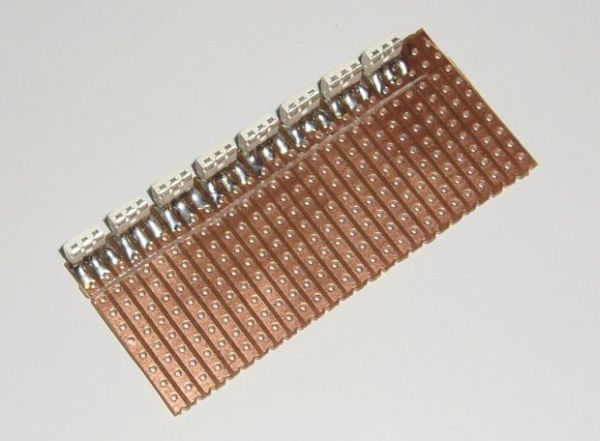
I have cut my board so that I have 26 holes by 10 holes.
Step 4
Solder in the LED’s and cut some tracks

I have used surface mount LED’s just to see how they would go (I have previously used through hole LED’s in a past project)
Solder the Red, Green and Blue connections to the board.
The three connections on the top are the cathodes. (this may differ for your LED’s – give them a quick check with your multimeter to verify)
You will also notice I have cut a line through the tracks connected to the LED’s. This is so we can solder in some series resistors to limit each LED’s current.
IMPORTANT NOTE: You need to make sure that the bottom LED is connected as your least significant LED. I.E. this led will connect to PORTA pin 0, PORTB pin 0 and PORT D pin 0. You then work your way up from there. Follow the schematic and you will be fine = )
Step 5
Solder in your resistors.
I have also used surface mount resistors to keep my project small, you may very well want to use through hole to make things a little easier.
The resistors solder in over the tracks that you have just cut.
Step 6
Cut some more tracks and solder in a ground wire.
Now that the resistors are in place, you will want to cut another line of tracks on the other side of these resistors, getting them ready to solder to the microcontroller. – see the first photo
Once done, get a length of uninsulated wire and solder it along the length of the LED cathodes. then solder it to the veroboard (this will be our ground connection) – see second photo
For more detail: The One Chip Spinning RGB POV Display with conversion software using PIC18f4680 microcontroller

