Ok, so there are heaps of immobilisers out there but with most of them, if someone has your keys, they have you car. What good is a car alarm with 3+ point immobilisation if someone manages to get the keys and of course the alarm remote.
This is a simple immobiliser based on a PIC12F629 and an ID-12 chip from innovations. This can be built for about $50.
Advantages:
The ID-12 chip is/can be remotely mounted away from the main PCB, behind a panel with no external components viewable.
If someone carjacks you or something like that (after you have started the car) then if they stop the car, it will not be startable again.
Cheap and effective
I apologise for the slight lack in detail. This was a project i done some time ago and it has been a long time since i touched it. I have posted this on here as it was requested by a few people. I will be happy to answer questions though.
Step 1: The Schematic and how it works
The PIC and the ID-12 are powered by a 7805 5v regulator via some basic filtering caps. The PIC is in an endless loop at this point, reading available data from the ID-12. Once a card/tag is read, it compares the string with up to 10 tags it has in EEPROM. If one matches, it activates the transistor which in turn activates the relay and the program stops. If there is no match, it just keeps waiting for data. The bi-colour LED indicates the status.
Initial setup is done by shorting the jumper and then reading up to 10 tags in sequence. This overwrites each tag if it’s alreading in eeprom.
I know the schematic is hard to read, click on the ‘i’ in the top left then click on the ‘original file’ link for an uncompressed version…
Step 2: PCB
The PCB is fairly straight forward when teamed up with the schematic. There’s not much to it…
Print, transfer, etch, drill etc.
The ID12 is wired in standard ASCII mode. The only connections needed are:
Pin 1: GND
Pin 2: +5v
Pin 7: GND
Pin 9: Data
Pin11: +5v
This means you only need 3 wires going to the ID-12. The others can be jumpered on the chip. If the run is long (more than say 20cm), I would suggest the use of shielded cable as cars are electrically noisy and it might cause dodgey readings. 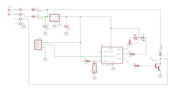
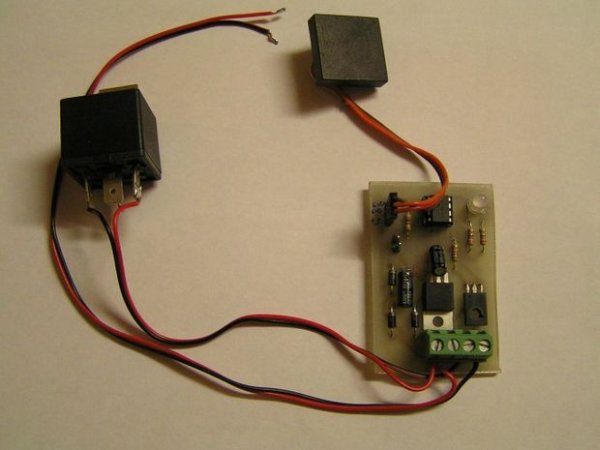
Step 3: All put together
Once you have the PCB done, solder it all up and program the chip with your fav. programmer. HEX file attached.
For debugging, you can connect pin 2 (GPIO5) and a ground pin to the serial port of a PC’s Rx and ground @ 9600 baud to see the actual tag values and what the chip is doing. However, it may not work properly on all PC’s without the addition of a max232 chip as it is only pseudo RS232 and not true levels. Not that i have come across any in recent times.
For more detail: RFID Car immobiliser with PIC12629