Design Goal:
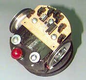
The JavaBot1 is a small line following robot designed to follow a black line drawn on a dry erase board. It is designed to follow very tight curves. The software still has lot’s of room for improvement but works well as is.
Motive Power:
The JavaBot1 uses 2 Cirrus CS-70 servos that have been modified
for full rotation and have had their controller boards removed to
convert them from servos to gear motors.
Servos are a common motive power for small robots due to their
low cost, ready availability, standardized sizes and the fact that it
only requires 1 bit on your processor to control the motor.
We initially tried this approach but found that the speed control was
very minimal with a finer control needed for this application. The
servo controller boards were then removed and the wires soldered
to the motor terminals and case ground. The motors were then
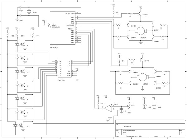
controlled by an H-bridge circuit to allow direction and speed control
with only 2 processor bits per motor. This is implemented as one bit for
direction and another bit for power/speed control per motor.
Sensors:
In order to follow the line I/R reflective sensors were used to
detect if a line was present or not. The sensors chosen are the
QRB1114 from QT Optoelectronics and have a focal point of
about 1/4 inch. They are available from DIGI-KEY.
Most line followers use 2 or 3 sensors of this type to do their
detection. This works but does not give the ability to follow
lines with very tight turns. An array of seven sensors arranged
in an “inverted V ” patternare bolted under the front of the robot
The sensors are wired with all the receivers connected in parallel and
fed to an LM311 comparator to set the threshold trigger level with it’s
output fed to a processor bit. The transmitter LEDs are connected
to a 74HCT138 with a current limiting resistor to VCC. This allows
the entire array to use 4 bits for the sensors.
Processor:
The PIC16F84 was chosen for it’s small size, easy reprogramability
and interrupts ( the fact that we manufacture a PIC processor
emulator also helped in this decision). It is clocked at 4 MHZ by
a ceramic resonator and is powered by 4 AA rechargeable batteries.
These same batteries power the motors. This is usually not recommended
since surges in motor current can affect the processors operation, but with
decoupling caps in place and the watchdog timer being used in the
software no problems were experienced. The watchdog could reset the
processor if it went stupid before you could ever see it act up.
Mechanical:
The servos were modified for full rotation by disassembling the servo
to gain access to the gear compartment. The main gear is then removed
and the stop that keeps it from rotating removed with an hobby knife.
The plastic key that keeps the feedback pot hooked to the main gear is
removed to allow full rotation without moving the feedback pot. The
servo controller was removed and the feed back pot removed as well.
The wires were removed from the control board and resoldered to the
motor terminals. The servos were reassembled and taped together.
For more detail: JavaBot1……….. A line following robot.