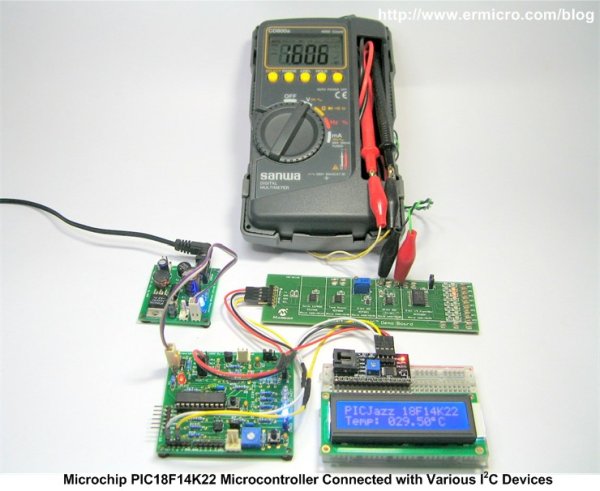
Summary of Interfacing the Microchip PIC18F Microcontroller Master Synchronous Serial Port (MSSP) to various I2C Devices
This article explains the Inter-Integrated Circuit (I2C) bus, introduced by Philips in 1980, widely used for communication between microcontrollers and devices like sensors and EEPROMs. It describes using the PIC18F14K22 microcontroller's Master Synchronous Serial Port (MSSP) configured in I2C master mode to control multiple I2C devices. The I2C protocol involves master-slave half-duplex communication over two lines (SDA and SCL) with pull-up resistors and uses unique 7-bit addresses for device selection, differing from SPI's chip-select method.
Parts used in the I2C Master PIC18F14K22 Microcontroller Project:
- Microchip PIC18F14K22 microcontroller
- Pull-up resistors for SDA and SCL lines
- I2C temperature sensor (example device)
- Analog to Digital Converter (ADC) with I2C interface
- Digital to Analog Converter (DAC) with I2C interface
- I/O Expander module with I2C interface
- EEPROM memory device with I2C interface
The Inter-Integrated Circuit or I2C (read as I square C) bus has been introduced in 1980 by Philips, and has become a de-facto world standard for data exchange between Microcontroller and various devices such as temperature sensor, ADC (analog to digital converter), DAC (digital to analog converter), I/O expander, EEPROM, and many more. With more than thousand different IC devices have been manufactured with an I2C-bus interface, making the understanding of the working principle of this I2C bus is an essential knowledge that has to be acquired by anyone who want to involve in the embedded world professionally or just as hobbyist.
In this project we will learn of how to use the powerful 8-Bit Microchip PIC18F14K22 microcontroller Master Synchronous Serial Port (MSSP) in the I2C master mode to control various I2C devices simultaneously
The I2C Bus Protocol
The I2C bus use master and slave communication principle which mean the slave will response to any master request and only one master or one slave could use the I2C bus at the time (half-duplex communication). Therefore the master and slave have to be connected known as “Wired OR” connection using the pull-up resistors for both the I2C serial data (SDA) and serial clock (SCL) as shown on this following picture.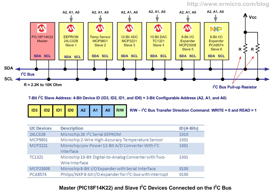
Unlike the SPI (Serial Peripheral Interface) slave devices, the I2C devices don’t have the chip select (CS) pin where the SPI master could simply drive the CS pin to logic “0” in order to communicate with the target SPI slave device, instead in I2C protocol the I2C master will transmit the I2C slave device unique address in order to communicate with it.
When the I2C bus is idle both of the SDA and SCL line will be logic “1”. When the I2C master want to start communicate first it will send the START signal by putting the SDA line to logic “0” then it start to send the 7-bit I2C slave address followed by 1-bit I2C bus transfer direction command (WRITE logic “0” or READ logic “1”). The 7-bits I2C slave address consists of the upper 4-bits (ID3, ID2, ID1, and ID0) whose are the device specific ID (identification) and encoded within each of the I2C slave device.
For more detail: Interfacing the Microchip PIC18F Microcontroller Master Synchronous Serial Port (MSSP) to various I2C Devices