


Summary of Logic Probe Plus using PIC12F683
This article describes a Logic Probe Plus project using a PIC12F683 microcontroller to measure voltage levels from 5V TTL to 24V PLC. The device features an input stage with a voltage divider for signal adaptation and an output stage with three LEDs (Yellow, Green, Red) to indicate high impedance, logic 1, or logic 0 states. It includes a low-power sleep mode activated by an internal timer after approximately three minutes of inactivity, reactivating only when a button is pressed.Parts used in the Logic Probe Plus:
- PIC 12F683 microcontroller
- Voltage divider components (R3, D5, D1)
- Three LEDs (Yellow, Green, Red)
- Internal oscillator (4MHz configured)
- GP1 pin (Analog input)
- GP2 pin (Digital input with PULL UP resistor)
- Secondary switch connected to ground
- Battery power source
The circuit is supplemented by an input stage which will adapt the signal to the levels between the microprocessor is able to work and another output stage that will visually show the state in which the point is measured.
The input stage to include a voltage divider between R3 D5 and D1, their role is to establish a fixed value (/ - 2.80) for the input of the microcontroller which means that is in a state of high impedance, ie without input signal. When we apply the input signal DATA IN this will vary the voltage drop at point H so that the reading as we discriminate if this is higher or lower than the reference voltage.
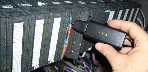
The output stage is made up 3 LED (yellow = high impedance, Green = Red = logic 1 and logic 0).
The program also has an internal timer to approximately 3 minutes between the microcontroller in sleep mode in which consumption will be minimal, to save the battery. And it will reactivate the program until you press the button, starting over allowing timing and take readings we require.
Focusing on the program of the microprocessor, this is configured to work with internal oscillation 4Mhz and configuring its pin so that analog reading take from point H by the GP1 pin, which is defined for a resolution of 10 bits, pin GP2 will also be defined as input and will be connected through a resistor (PULL UP) and a secondary switch to ground, which will be responsible for collecting the press that forced the interruption level change in GP2 While the interruption occurs loads a value (2000) as a timer to make a loop past work and this time will be placed the microcontroller in sleep mode.
For more detail: Logic Probe Plus using PIC12F683
- What voltage range can this probe measure?
The probe measures levels from TTL 5v up to PLC state levels of 24v. - How does the input stage adapt signals?
It uses a voltage divider between R3, D5, and D1 to establish a fixed reference value of approximately 2.80 for the microcontroller input. - What do the different colored LEDs indicate?
Yellow indicates high impedance, Green indicates logic 1, and Red indicates logic 0. - Can the device operate on low voltages?
Yes, the PIC 12F683 operates at 3vcc which allows it to work with low voltage requirements. - How long does the microcontroller stay in sleep mode?
The internal timer keeps the microcontroller in sleep mode for approximately 3 minutes to save battery consumption. - How does the user reactivate the program after sleep?
The user must press the secondary switch connected to GP2 to force an interruption level change and restart the timing. - What clock speed is used for the microprocessor?
The program is configured to work with an internal oscillation of 4Mhz. - What resolution is used for analog readings?
The GP1 pin is defined for a resolution of 10 bits when taking analog readings from point H.
Related projects
Automotive Voltage Monitor using PIC12F683
Description Recently I got a new motorbike and on my second trip out, with only 50 miles on the clock the rectifier/regulator...
Communication & Interfacing · PIC12F683EnvStick USB Temperature Sensor using PIC12F683
The EnvStick is cheap, homemade temperature sensor that plugs into a USB port. It provides a simple way to collect a room’s...
Sensors & Temperature · PIC12F683Metal detector robot using pic microcontroller
This project describes hardware and software I have developed which allows a small 8 bit PIC microprocessor to function as a single...
Meters & Test Instruments · PIC16F688Determine capacitance by measuring the charging time using PIC16F688
When TEST botton is pressed, RA3 pin is set to "1". R2 and R3 are divide the voltage to 1/2 Vra3 which...
Meters & Test InstrumentsFrequency Meter Using Microcontroller
This tutorial simply states how to calculate frequency of a pulse source using a microcontroller. Story https://youtu.be/NAoj-HLRIro This tutorial simply states how...
Meters & Test Instruments · PIC16F84ADigital thermometer with PIC16F84 circuit
This electronic project is a very simple thermometer that is based on the PIC16F84A microcontroller, designed by Microchip. Why to use a...

Ibrar Ayyub
I am an experienced technical writer holding a Master's degree in computer science from BZU Multan, Pakistan University. With a background spanning various industries, particularly in home automation and engineering, I have honed my skills in crafting clear and concise content. Proficient in leveraging infographics and diagrams, I strive to simplify complex concepts for readers. My strength lies in thorough...