Real Time Clocks, as the name suggests are clock modules. They are available as integrated circuits (ICs) and manages timing like a clock. Some RTC ICs also manages date like a calendar. The main advantage is that they have a system of battery backup which keeps the clock/ca lender running even in case of power failure. A very small current is required for keeping the RTC alive. This in most case is provided by a miniature 3v lithium coin cell. So even if the embedded system with RTC is powered off the RTC module is up and running by the backup cell. This same technique is used in PC timing also. If you have opened your computer case you will notice a small coin cell in the mother board.
In this tutorial we will learn to use a very famous RTC IC named DS1307. The DS1307 is described in the datasheet as follows
The DS1307 is a low-power clock/calendar with 56 bytes of battery-backed SRAM. The clock/calendar provides seconds, minutes, hours, day, date, month, and year information. The date at the end of the month is automatically adjusted for months with fewer than 31 days, including corrections for leap year. The DS1307 operates as a slave device on the I2C bus.
So the aim of the project will be to access the DS1307 registers, read time
- Access the DS1307 registers i.e. read/write data to/from the DS1307 IC
- Format the read data and display in LCD
- Ability to get time from user and store it to DS1307. This provide means to setup the RTC module with correct time.
DS1307 Internal Registers
From software point of view the DS1307 is just a collection of some 8 bit registers. You can read these register to obtain the current time and date. You can also modify them to hold the correct time. After that the DS1307 keeps then updated with current date and time. The following registers are there.
| ADDRESS | BIT7 | BIT6 | BIT5 | BIT4 | BIT3 | BIT2 | BIT1 | BIT0 | FUNCTION | RANGE |
| 00H | CH | 10 SECONDS | SECOND | SECOND | 00-59 | |||||
| 01H | 0 | 10 MINUTES | MINUTES | MINUTES | 00-59 | |||||
| 02H | 0 | 12 | 10HR | 10HR | HOUR | HOUR | 1-12+AM/PM OR | |||
24 | am/pm | |||||||||
| 03H | 0 | 0 | 0 | 0 | 0 | DAY | DAY | 01-07 | ||
| 04H | 0 | 0 | 10 DATE | DATE | DATE | 01-31 | ||||
| 05H | 0 | 0 | 0 | 10MONTH | MONTH | MONTH | 01-12 | |||
| 06H | 10 YEAR | YEAR | YEAR | 00-99 | ||||||
| 07H | TO KEEP THINGS SIMPLE I HAVE SKIPPED THE CONTROL REGISTER THIS IS USED FOR SQUARE WAVE GENERATION ON PIN7 | |||||||||
| 08-3FH | 56 BYTE RAM | 00h-FFh | ||||||||
The register uses BCD (Binary Coded Decimal) for storing the values. For example take register at address 01h, it stores the MINUTES. Say it is 37 minutes. Then it will be stored as follows.
Fig. : BCD Format in DS1307 Registers. |
The DS1307.c and DS1307.h provide easy access to the registers. I have provided just two functions that allows you to read and write the DS1307 registers.
/***************************************************

Function To Read Internal Registers of DS1307
---------------------------------------------

address : Address of the register
data: value of register is copied to this.


Returns:
0= Failure
1= Success
***************************************************/

uint8_t DS1307Read(uint8_t address,uint8_t *data)


/***************************************************

Function To Write Internal Registers of DS1307
---------------------------------------------

address : Address of the register
data: value to write.


Returns:
0= Failure
1= Success
***************************************************/
uint8_t DS1307Write(uint8_t address,uint8_t data)
These functions depends on the I2C library. The I2C (Inter IC Communication) is a popular communication protocol between ICs. The DS1307 and our AVR ATmega8 communicates using the I2C bus. I will give more details on I2C in a separate tutorial.
A Simple RTC Module
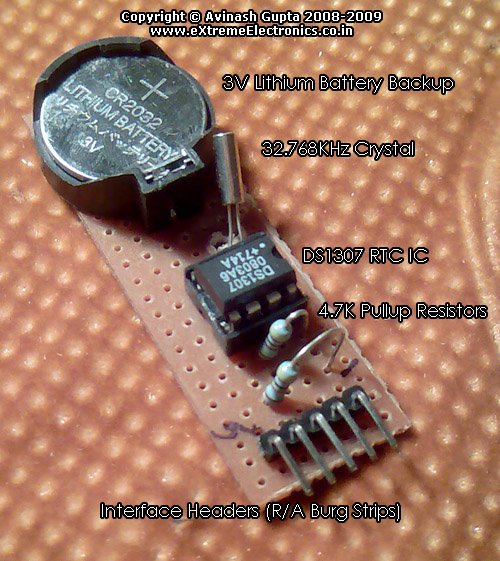
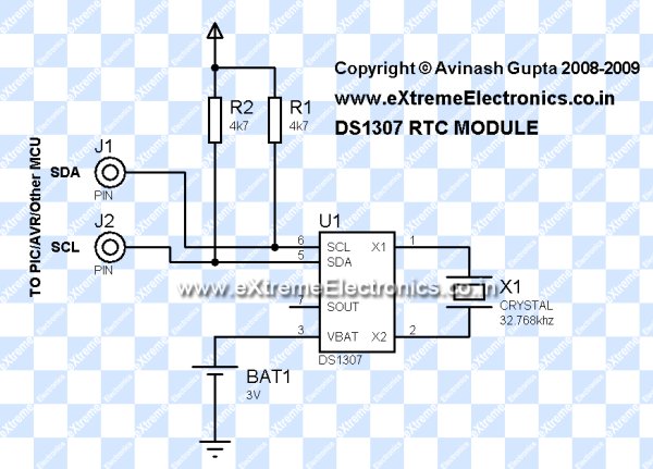
The DS1307 require an 32.768KHz crystal, a 3v lithium battery and 2 pull up registers to function. So I will make a small PCB that will hold all these. The image of module is shown below. The module can be connected to development boards using female-female burg wires.
Once you have the RTC Module ready you can connect it with your favorite MCU like PIC or AVR or any other MCU. In this tutorial I will connect it with AVR ATmega8 MCU, I will also interface it with PIC MCUs latter on.
AVR ATmega8, DS1307 RTC Interface Example with LCD Module
To make a complete usable example we will connect a 16×2 LCD Module, and 3 push buttons.
avr-gcc software
The full software for the example is written in C language and compiled with avr-gcc. The whole software is very modular. Following software modules are used.
- LCD Interface modules for handling the display device. More detail is given on these pages.
- LCD Interfacing library for Atmel AVR MCUs
- LCD Interfacing library for Microchip PIC MCUs
- Low Level I2C Interface Library. This handles the data communication using the hardware I2C module present inside AVR/PIC MCUs.
- For Atmel AVR MCUs (Yet to be written)
- For PIC16 MCUs.(Yet to be written)
- For PIC18 MCUs.(Yet to be written)
- DS1307 Module : This module built on top of above I2C module help in reading/writing data to and from the DS1307 chip. Functions are very simple and documented inside the .c and .h files itself.
- The main application module RTC.c is the application software that uses the above modules to communicate with both the LCD and DS1307 chip. It also manages the handling of UI (User Interface) by the help of 3 push buttons.
Fabrication Instructions
Assemble the circuits according to the circuit diagrams shown above. Burn the hex file (download link given at the end of article) to an ATmega8 using a suitable programmer. Set the fuse byte as followsLOW=21 HEX HIGH=D9 HEX . Apply power to the circuit and adjust the LCD Contrast Pot until the display is clear. The initial time should be shown as 00:00:00. Now press the “menu” key to enter the main menu. Use the LEFT and RIGHT Key to move between options and ENTER to select an item. The main menu has the following options.
- Set Time
- Set On Time (NOT IMPLEMENTED YET)
- Set Off Time (NOT IMPLEMENTED YET)
- Quit
For more detail: Interfacing DS1307 RTC Chip with AVR Microcontroller