Summary of CNC Controller Motion Schematics (Rev. D) using pic microcontrollers
This article details the schematics and components for a CNC motion controller (Revision D). It covers the power supply, I/O microcontrollers, RS-422 signaling, limit switches, X/Y/Z axis drivers using L298 H-Bridges, solenoid control, and PCB layout files. The text also lists specific manufacturing issues found in this revision, such as incorrect hole spacing, connector mismatches, and component labeling errors.
Parts used in the CNC Controller Motion Schematics:
- 110VAC Power Source
- Power Switch SW1
- Fuse F1
- Transformer T1
- Full Wave Bridge Rectifier BR1
- Filter Capacitor C31 (10,000µF)
- 24VDC Cooling Fan
- Voltage Regulators VR1, VR2, VR3
- I/O Microcontroller U11 (PIC16C745 or PIC16F876A)
- MAX232 Level Converter U17
- Differential Driver U13
- L298 H-Bridge U6
- Schottky Diodes D1 through D8
- PIC16F676 Microcontrollers
- Micron DIN Connectors N1 through N4
- Mini-DIN8 Connectors N6 and N7
Table of Contents
- Introduction
- Power Supply
- I/O Microcontroller
- RS422 and Limit Switches
- X, Y, Z, and Z Axes
- Selenoid and Motor Control
- Printed Circuit Board
- Issues
Introduction
The parts list is kept in a separate file.
Power Supply
The power supply schematic is shown below:
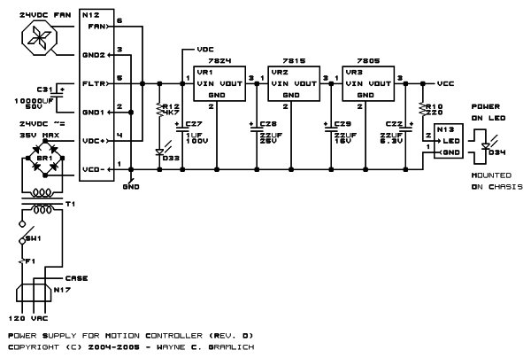
The power supply is pretty mundane. The 110VAC comes in on connector N17 and is hooked in series with a power switch SW1, a fuse F1, and the primary coil of transformer T1. The secondary coil of T1 produces 24VAC at 12 Amps and is routed through the full wave bridge rectifier BR1 and onto the controller board at connector at pins 1 and 5 of N12. A large off-board filter capacitor of 10,000µF (C31) is connected to the controller board at pins 2 and 5 of N12. In addition, a 24VDC cooling fan is connected at pins 3 and 6 of N12. Resistor R12 and red LED D33 will bleed off the charge of C31 when power is turned off. As long as D33 is lit, there is charge on the capacitor and extra care should be taken. The 24V primary coil is rated in RMS (Root Mean Squared), so the actual peak voltage is 24V/.707 or approximately 35 volts. The unregulated voltage is used by the stepper and selenoid drivers as VDC. The unregulated voltage is stepped down through VR1, VR2 and VR3 to produce the 5 volts needed by the digital circuitry. The reason for using 3 voltage regulators is because 1) the stepper motors and selenoid chopper circuits will be causing a fair amount of roughness on the unregulated voltage and 2) the amount of heat generated will be spread across 3 voltage regulators rather than just 1. While the schematic does not show it, there are test points for each of the voltage regulators on the PCB. Lastly, power on is indicated by the green LED D34 which is current limited by R36. LED D34 is mounted off board on the chasis.
I/O Microcontroller
The I/O microcontroller U11 is only needed if the user intends to use either the RS-232 connector N9 or the USB (Universal Serial Bus) connector N10. The PIC16C745 is needed to support both USB and RS-232, whereas a simpler PIC16F876A is can be used if only RS-232 support is needed. The microcontroller firmware emulates the 25-pin DB25 parallel port connector N11. The microcontroller can detect the usage of the parallel port when pin 1 of N11 is pulled low; otherwise, the microcontroller detects that there is no parallel port in use by having pin 1 pulled high by R18 and assumes that some form of serial communication is going to be used. All of the RESET lines for all of the microcontrollers are tied together and pulled high by R19. The U17 MAX232 RS-232 level converter chip is used to convert between RS-232 levels and microcontroller logic levels. Connector N10 is used for USB communication. Resistor R16 and capacitor C21 are used to indicate to the USB host that this is a slow speed line. Lastly, N14 is used to connect to an off board red fault LED D35 through current limiting resistor R9.
RS-422 and Limit Switches
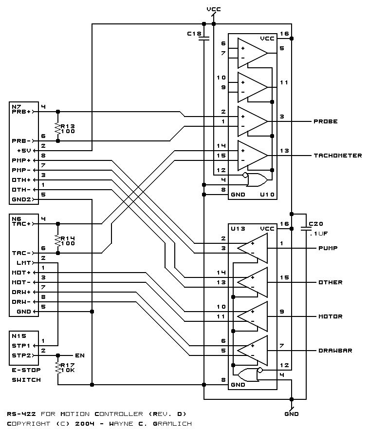
Differential RS-422 is used for off board signalling because of the excellent high noise rejection capabilities. Long wires tend to behave like antennas and pick up the noise from flouresent light bulbs and local HAM radio operators. RS-422 is able to avoid most of those problems. All control and sense operations are bundled into two 8-pin mini-DIN connectors N6 and N7. There was no extra board edge space fore additional conntectors. All logical level signals are converted to RS-422 voltage via the quad differential driver U13. The motor and drawbar signals are routed to N6 and the pump and “other” signal is routed to N7. In addition, two RS-422 signals are converted to regular logic levels by U10. The probe signal comes from N7 and the spindle tachometer signal from N6. Resistors R13 and R14 are line termination resistors. Lastly, any limit switches are connected together in series from N7 pin 2 to N6 pin 2. The switches are normally closed and only open when some sort limit condition is encountered. In addition, the normally closed emergency stop switch is connected across N16. If there is any open circuit in the limit switch and emergency stop chain, the EN enable line is pulled low via R17. Otherwise, the +5 volts on pin 2 of N7 asserts the EN enable line.
X, Y, Z, and Z Axes
The X Axis schematic is shown below:
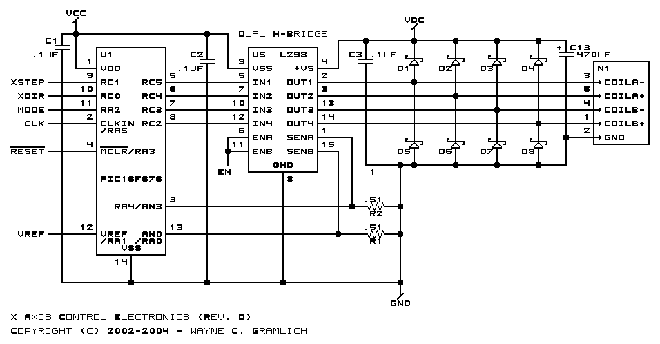
The X axis is controlled by PIC16F676 microcontroller U1. It drives the L298 H-Bridge U6. Current sensing is done via resistors R1 and R2. The maximum current through the L298 is 2 amps, so the maximum voltage drop across the .5 ohm sense resistors is 1 volt for a maximum total power disappation of 2 watts. L298’s do not come with clamping diodes, so those are provided externally via schottky diodes D1 through D8. The stepper signals are send out via 5-pin DIN connector N1. The microcontoller is repsonsible for reading the sense voltage using its ADC (analog to digital converter) and manipulating the H-bridge to ensure that no more than 2 amps average flows through each stepper motor winding. Capacitor C13 provides 470µF of additional filtering of VDC close to the L298.
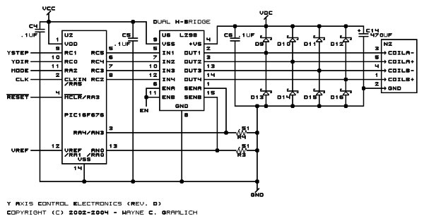
The Y Axis schematic is shown below:

The Y axis is the same as the X axis above, with different component labels.
The Z Axis schematic is shown below:
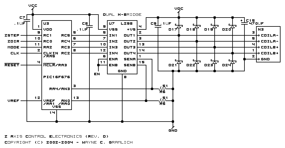
The Z axis is the same as the X axis above, with different component labels.
Selenoid and Motor Control
The selenoid and motor control schematic is shown below:
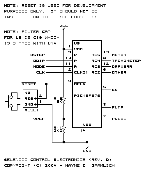
All control is performed by microcontroller U9. Since there was no other logical place to put it, resistors R15 and R11 form a voltage divider of approximately 1.25 volts that is fed into the VRef pins of the other axis microcontrollers. Lastly, a reset button can be attached to N8 to reset all microcontollers; this button is for firmware development purposes only and should not be installed on the final chasis. The microcontroller U9 is responsible for sensing if the EN signal on pin 5 goes low and quickly disabiling all of its motor, tachometer, drawbar, and “other” signals.
Printed Circuit Board
The printed circuit board files are listed below:
- Artwork
- Back
- Front
- RS274-X `Gerber’ Artwork
- RS274-X `Gerber’ Solder Side
- RS274-X `Gerber’ Component Side
- `Excellon’ Drill File
- Tool File
Issues
The following issues are present on revision D of the motion controller board:
- The upper left mounting hole is too close N7. Luckily there is room to move it down and to the left.
- The holes for Capacitor C27 are .1″ too far apart.
- The holes for N1 through N4 are incorrectly staggered. The two outside and middle holes are not close enough to the outside edge by .1″ inch. The remaining too holes are are to close to the outside edge and need to be moved in by .1″.
- The upper right mounting hole is too close close to N14.
- The lower left mounting hole is quite cramped and is quite close to the N11.
- N9 should be a female DB9 connector.
- N11 should be a ?? DB25 connector.
- N9 needs to have a corner of its plastic hacked away to make room for C24.
- The mechanical holes for N10 are way too large.
- N11 needs to have a corner of its plastic hacked away to make room for C23.
- N11 needs to have a corner of its plastic hacked away to make room for the mounting screw. This may not be easy to fix.
- The mini-DIN8 connectors, N6-N7, have an extra mechanical connector in the middle. Also, the pins are arranged symetrically, this is no pin offset to force polarization. I probably used the wrong specification sheet and got away with it by snipping off the middle mechanical attach.
- Speaking of the mini-DIN8 connectors, I foolishly thought that a male mini-DIN8 to male mini-DIN8 cable would be wired straight throuh pin for pin. Nope. The most common ones out there are for the Apple MacIntosh serial cables and some wires are straight through and others are crossed.
- C22 has the + and – for the capacitor polarity reversed.
- R10 is mis-labeled as R36 on the artwork.
- Pin 6 of U11 (RA4) is an open drain output and needs a 10K pull-up resistor. I get burned by this every time, no matter how hard I try to avoid it! Pin 4 (RA?) is a better choice.
- The voltage divider for VRef on the PIC16F676’s should be done using R15 and R11 should be done using precision resistors. The 5% stuff does not provide a reliable enough result.
- Vref does not appear to be necessary; just drop it entirely.
- Olimex accidentally shorted out pins 8 and 10 on U3. Perhaps reroute the trace to pass a little less closely to pin 10?
Source : CNC Controller Motion Schematics (Rev. D)
- How does the system handle noise on long wires?
Differential RS-422 is used for off-board signaling because it offers excellent high noise rejection capabilities against sources like fluorescent lights. - What is the purpose of the three voltage regulators?
Three regulators are used to spread heat generation and isolate roughness caused by stepper motors and solenoid chopper circuits from the digital circuitry. - Can the microcontroller detect parallel port usage?
Yes, the microcontroller detects parallel port usage when pin 1 of connector N11 is pulled low; otherwise, it assumes serial communication is being used. - How are limit switches connected in the circuit?
Limit switches are connected in series from N7 pin 2 to N6 pin 2 and are normally closed, opening only when a limit condition is encountered. - What limits the current through the L298 H-Bridge?
Current sensing resistors R1 and R2 monitor the flow, and the microcontroller manipulates the H-bridge to ensure no more than 2 amps average flows through the motor windings. - Why are external clamping diodes required for the L298?
The L298 chips do not come with built-in clamping diodes, so Schottky diodes D1 through D8 must be provided externally. - What issue exists with the mounting holes in Revision D?
The upper left mounting hole is too close to N7, and the holes for capacitors C27 are .1 inch too far apart. - Is the VRef voltage divider reliable in the current design?
No, the 5% resistors used in the voltage divider do not provide a reliable enough result, and precision resistors are recommended. - What problem was found with the mini-DIN8 cables?
The designer mistakenly assumed male-to-male cables were wired straight through, but common ones use crossed wires similar to Apple Macintosh serial cables. - Which pins on U11 require attention regarding output configuration?
Pin 6 of U11 is an open drain output that requires a 10K pull-up resistor, whereas Pin 4 is suggested as a better choice.