Summary of How to make a JDM Programmer
This article explains building a JDM programmer using an RS232 DB9 serial port to program the PIC18F4550 microcontroller. The JDM programmer is a cost-effective, simple tool compatible with Winpic800 software for burning hex code into the microcontroller. It warns against using USB to DB9 converters and recommends a desktop PC with a native serial port. The article provides a modified schematic tailored for programming 40-pin PIC18F4550 chips, removing unnecessary components to simplify the design. This programmer is ideal for beginners before upgrading to advanced tools like Pickit3.
Parts used in the JDM Programmer for PIC18F4550:
- RS232 DB9 9-pin Serial Connector
- Resistors (various values depending on schematic)
- Diodes (specified in schematic)
- Transistors (as per schematic)
- Capacitors (as per schematic)
- Microcontroller PIC18F4550 (for programming)
- PCB or perfboard for mounting components
(PIC18F4550 Programming)
Hardware | Schematic | Complete Description
This JDM programmer works with a RS232, 9-pin(9 wire) DB9 Serial connector on your computer, and is used for loading Source Code (hex files) into your microcontroller. JDM programmers are Cheap and very easy to make. JDM programmer that we are going to make will be used for loading the code into microcontroller board. You can probably buy this JDM Online or from some Electronic store but if you are going to make one for yourself then, total spending for all components and board will cost you less than half of the actual price of the JDM that you will get in any electronic store.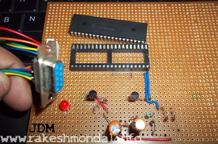
Overview JDM
This jdm programmer responds, or lets us to burn the program into the microcontroller chip through small software known as winpic800. Winpic800 is compatible with pic18f4550 and JDM serial programmer. It works with lot of other hardware too, which are similar to JDM programmer, like the [GTP-USB] but it costs around 60 € from their official website. So it’s a good option for beginners to stay with JDM programmer as cheap alternative in the early stages. Later for a better programmer I recommended pickit3 from microchip which makes it easier to program with a USB port. As of now with this JDM programmer we are going to program PIC18F4550 USB Interface Board for FIRST TIME BURNING OF CODE INTO THE CHIP
This JDM programmer uses RS232 DB9 port to program the code into the microcontroller. I recommend do not use a laptop for JDM programmer. Usually now a days laptop’s does not comes with a DB9 serial port, so if you are thinking to use a USB to DB9 converter cable for doing this job then its a bad idea. Don’t even think about USB to DB9 converter, it just won’t work. So I recommend use a Desktop Computer which comes with an inbuilt DB9 Serial port. If you are thinking of a USB programmer then pickit2 or pickit3 will be a good option.
Schematics and Components
I found a nice tutorial about long time ago for making this JDM programmer. The name of the device was JDM EXTREME. I don’t remember where I found it, but I still have Schematic for making it. I have modified the actual schematic according to our need for this programming 40 pin microcontroller. I have posted both the actual Schematic and modified Schematic below. FOLLOW THE SECOND SCHEMATIC FOR 40PIN Microcontroller board.
The 1st one is actual schematic which can be used for verities of JDM supported microcontrollers (you can modify it according to the type of microcontroller you want to use) and second one is the modified schematic (removed all non-required components for our microcontroller) which we are going to use for 1st time programming of our pic18f4550 USB interface board.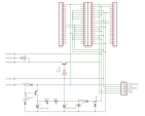
SCHEMATIC -2 ( follow this one for your hardware)
In the second schematic all the components that we don’t required for our 40 pin microcontroller is roughly removed. Please don’t mind some left out lines in the schematic 🙂 , just ignore the incomplete lines and follow hard lines. Follow basics of schematic, DOT shows connectivity of lines in schematics , Ignore the incomplete lines that I have left in the second schematic.
For more detail: How to make a JDM Programmer