High voltage definitely would hurt you and potentially could kill you! So please be careful. If you don’t know what precautions to take, please find someone who does. You’ve been warned.
Edit: fellow instructable brought up a good point. Thanks Spark Master!
“I would mention you will probably void any Home Owners Insurance you have if you do this in NYC. Ask the electrical inspectors listed in the phone book for your area.”
Step 3: Charger Surgery
I replaced the input wire with a slightly longer wire.
I also removed the USB connector because plugging in a USB cable would have taken more room.
I then put everything back into its original container.
Step 4: High Voltage Wiring
Obviously, we want the relay to switch the live wire instead of the neutral.
I opted to break one of the tabs that joins the two outlets. This allowed me to wire up one of the outlets to be always on, while the other outlet is switched by the relay.
Step 5: ESP8266 & Relay Wiring
The wiring is fairly simple, so I opted to solder everything right around the ESP8266 instead of creating a custom PCB.
You could pretty much use any ESP model. I ended up using an ESP12.
The pushbutton switches and USB to Serial module are only necessary to program the ESP. That’s the reason for the “header pins” on the ESP:
- Ground
- RX
- TX
- GPIO0 (bring to ground at power up to put ESP in program mode)
- Reset (optional)
As you can see in the photos, instead of mounting the relay module on a PCB, I use the relay module as the center piece. I mounted the AMS1117 LDO (Low Drop Out voltage regulator) and the ESP8266 around the relay module. The wires are stiff enough to hold the ESP in place. I discovered that the 3.3V output of the LDO is available at the middle pin AND at the heatsink which is more convenient structurally to hold the ESP in place.
Step 6: Programming


When it comes to software, there are many options. The simplest one I found at the writing of this Instructable is Blynk. Download the free app onto your iPhone or Android. Register and get the AuthToken.
In the Arduino IDE, open Library Manager (Sketch > Include Libray > Manage LIbraries…) to install blynk library.
Under File > Examples > Blynk > BoardsAndShields > ESP8266_StandAlone
Modify the sketch to include your AuthToken, home WiFi SSID and password.
Hold GPIO0 to ground (using a switch of just temporarily wire it to ground) while powering it up or pressing reset.
Once the upload is done, you no longer need the USB to Serial module.
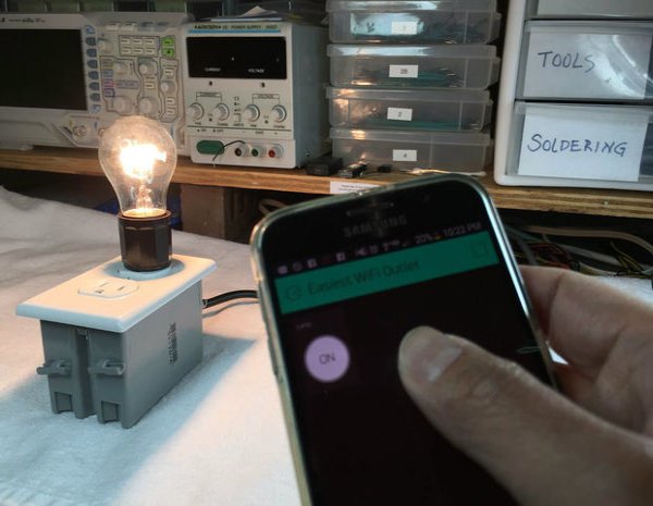
For more detail: DIY WiFi Outlet using ESP8266