Summary of 4 Bit LCD interfacing and programming with PIC Microcontroller
This article explains interfacing a 16×2 LCD with a PIC microcontroller using 4-bit mode to save data pins. It details the initialization sequence, including reset commands and nibble-based data transmission. The guide covers setting the RS pin for data vs. commands, pulsing the Enable pin, and handling upper and lower nibbles via bit shifting.
Parts used in the 4-Bit LCD Interfacing Project:
- 16×2 LCD
- PIC Microcontroller
- Data lines D4-D7
- RS pin
- RW pin
- EN pin
LCD displays operate in two modes 4 bit and 8 bit mode. We all might have been familiar with 8 bit mode which is used widely in several systems. But 4 bit mode is something which many of us is not aware of. This mode has some advantages over the 8 bit mode out of which reduction of dedicated data pins is most important. This tutorial will teach you 4 bit LCD interfacing in 4 bit with your controller as well as programming it.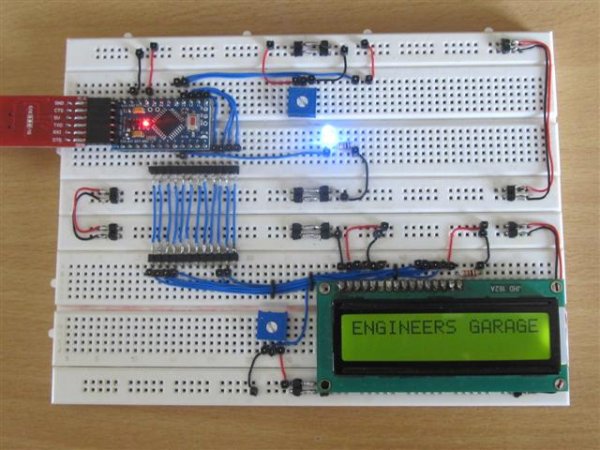
WHAT IS 4 BIT MODE:
We all knew that LCD consists of 8 data pins D0-D7 to receive the data and commands from the Microcontroller. However when developing a complex systems dedicating a complete port i.e 8 pins might be a drawback. To overcome this the LCD controller is capable of running in dual modes 8 bit and 4 bit mode.
8 Bit mode is a normal mode which uses 8 data lines, rs and enable for lcd functioning, see programming LCD in 8 bit mode. However in 4 bit mode only 4 lines D4-D7, along with RS,RW and EN pins are used. This will save us 4 pins of our controller which we might employ it for other purpose.
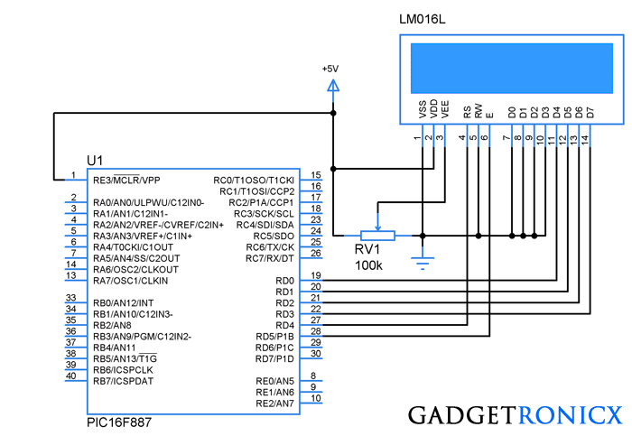
In 4 Bit mode the data bytes are sliced into two four bits and are transferred in the form of a nibble. And the rest of the pin functions such as RS,RW and EN remains same. The above design illustrates the connection diagram of a 16×2 LCD with PIC microcontroller in 4 bit mode.
INITIALIZING THE LCD:
The first step in coding the LCD is initializing the LCD connected by giving the commands as input through the data line D4-D7 in the fom of Nibbles. For initializing the LCD following a specific reset sequence should be given and then initialized to follow the 4 bit mode.
- Place the byte in D4-D7 pins of LCD and set the EN pin to high and then make it low with time delay of 10ms between them.
- Send 28H command to use 2 lines 5×7 matrix in 4 bit mode.
- Send 0FH for making the LCD,cursor and Cursor blinking ON.
- Send 06H for incrementing cursor position.
- Finally 01 and 02 for clearing screen and returning home.
DATA/COMMAND TRANSMISSION TO THE LCD:
The data transmission to a LCD must be performed by means of assigning logic states to three pins RS and E. R/W pin is not needed so we can ground it as shown in the schematic diagram. The data is send to the module by following these steps.
- RS pin should be high to convey LCD a data transmission is going to take place.
- Place the Upper nibble in the lower four bits of Port 2 by means of bit shifting and mask the upper four bits.
- Pulse En pin from high to low with certain time delay for transmission to complete.
- Now place the lower nibble and mask the rest of the bits, then repeat step
For more detail: 4 Bit LCD interfacing and programming with PIC Microcontroller
- Why use 4-bit mode over 8-bit mode?
It reduces the number of dedicated data pins required by half. - Which data pins are used in 4-bit mode?
Only pins D4 through D7 are used along with RS, RW, and EN. - How is data transferred in 4-bit mode?
Data bytes are sliced into two four-bit nibbles and transferred sequentially. - What is the first step in initializing the LCD?
Place a byte on D4-D7 pins, set the EN pin high, then low with a 10ms delay. - What command initializes the LCD for 2 lines and 5×7 matrix?
The 28H command is sent to configure 2 lines and a 5×7 matrix in 4-bit mode. - How do you enable the cursor and blinking?
Send the 0FH command to turn on the LCD, cursor, and cursor blinking. - What happens when you send the 06H command?
It sets the LCD to increment the cursor position automatically. - How should the R/W pin be connected if not needed?
The R/W pin can be grounded as it is not required for this operation. - What logic state must the RS pin have for data transmission?
The RS pin must be set high to indicate that data transmission is taking place.