Intro:
Chronograph for Air Cannon
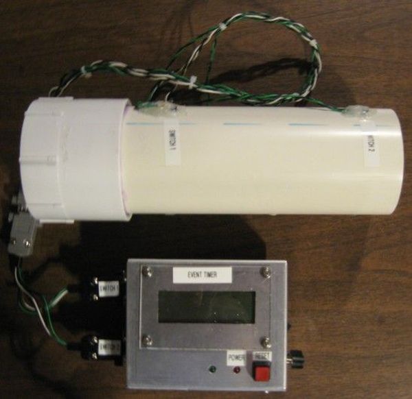
This chronograph project consists of a sensor assembly and timer circuit box that can be used to measure the muzzle velocity of a projectile fired from an air cannon.
I originally built this setup for use with a large air cannon with a 3″ bore.
The sensor assembly is attached to the end of the air cannon barrel. It contains infrared sensors used to detect the passage of the projectile. A microprocessor measures the time it takes for a projectile to travel a known distance and displays it on an LCD. From this information, the velocity can be easily calculated.
Step 1:
Overview of Operation
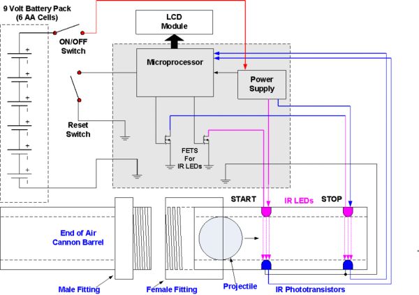
Below is a block diagram of the timer box and sensor assembly system. The sensor assembly is shown at the bottom of the diagram, with a round projectile traveling through it. The functional blocks within the grey box are located on the PCB. The switches, connectors, and LCD module are mounted on the case of the timer box.
The sensor assembly consists of a length of 3” diameter PVC pipe, with the two IR sensor pairs mounted 6 inches apart. The sensor assembly has a threaded fitting on one end, which allows it to be easily connected to another threaded fitting on the end of the barrel.
The timing circuit initially monitors the first sensor, waiting to detect that the beam has been broken by the projectile. After the first beam is broken, the processor starts an internal timer to record the time that has elapsed since the beam was broken. The software then begins monitoring the second sensor. When that beam is broken, the timer will be stopped. The processor then displays the time elapsed between the breaking of the beams on the LCD.
Step 2:
Circuit Description
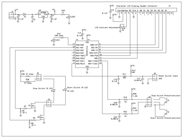
The schematic for the timer and sensor set up is shown below. A brief description of the function of each componenent is as follows.
Power Supply
U4 is a 5 volt regulator used to produce the regulated 5 volt “VDD” supply for the microprocessor. C1 and C2 are input filter capacitors for U4, used to stabilize the input voltage. C4 is an output filter capacitor for regulator U4, used to stabilize the output voltage. LED1 is a “power on” indicator, and R43 limits the current through LED2.

Microprocessor
The microprocessor U1 monitors the two sensors, measures the time elapsed between the breaking of the two sensors, and configures the results for display on the LCD module. C14 is the bypass capacitor for the VDD input of the microprocessor.
A reset switch is included, so the program can be restarted for another measurement without having to remove power to the circuit. R12 keeps the reset input of the microprocessor pulled high when the button is not pressed. R11 and C16 form a low pass filter to keep the microprocessor from being reset due to electrical noise. C17 is to arrest any ESD spikes that may come in on the switch lines. J5 is the connector for the SPST momentary reset switch on the front panel.
LED1 is a general purpose indicator that is mounted on the front panel. It can be used to provide feedback to the user to indicate any conditions that might be necessary. R15 is the current limiting resistor for LED2
Sensor Interface
Each sensor pair consists of an infrared LED and a phototransistor. The pair is mounted so that the light from the LED shines across the pipe to the phototransistor on the other side. When the phototransistor is illuminated by the LED, it is “ON” and it pulls its collector low. When the beam is broken and the phototransistor is no longer illuminated, it turns “OFF” and its collector is pulled high by the pull up resistor on the PCB.
IR LED Drive
The IR LEDs themselves are located on the sensor assembly. The microprocessor can turn each IR LED on or off. Once both the sensors have tripped, there is no longer a need for the LEDs to be illuminated, so they are shut off at that point. This is not strictly necessary, but since the unit is battery powered this feature was included to extend battery life.
R38 and R30 are current limiting resistors for the two infrared LEDs. Q1 and Q2 are used to turn the LEDs on or off. R6 and R8 are pull down resistors o the gates of Q1 and Q2, to keep them off when the microprocessor pins are floating during reset. R7 and R9 are not strictly necessary, but they are included here to limit any problems with ringing on the gate when the FETs are turned on or off. They can be replaced with jumper wires if there are no problems with ringing.
For more detail: Chronograph for Air Cannon using PIC16F628A microcontroller


