Week 01
January 10, 2012 (1 hour):
Met as a team after class to discuss preliminary project proposal.
January 12, 2012 (2 hours):
Met as a team after class to finish writing preliminary project proposal.
WEEK 01 SUMMARY
Accomplishments: Submitted preliminary project proposal.
Weekly Work Total: 3 hours
Project Work Total: 3 hours
Week 02
January 17, 2012 (2 hours):
Met as a team to formulate PSSC for presentation in class on January 25th.
January 19, 2012 (3 hours):
Met as a team to finish the final project proposal.
January 20, 2012 (1 hours):
Researched Parts.
WEEK 02 SUMMARY
Accomplishments: PSSC and project proposal finalized.
Weekly Work Total: 6 hours
Project Work Total: 9 hours
Week 03
January 22, 2012 (3 hours):
Met as a team to research parts and set up PSSC Presentation
January 23, 2012 (3 hours):
Made the PowerPoint for the presentation. Talked to TA and he suggested that writing a usb driver for XBee would not be feasible because it is really complicated. Thought of using IMUs for motion capture, but wasn’t sure if the magnetometer was needed.
January 25, 2012 (1 hours):
PSSC Presentation
January 26, 2012 (3 hours):
Met as a team to finish the PCB layout homework. Finalized on the IMU without the magnetometer.
WEEK 03 SUMMARY
Accomplishments: PSSCs Finalized, PCB layout tutorial finished
Weekly Work Total: 10 hours
Project Work Total: 19 hours
Week 04
January 29, 2012 (2 hours):
Met as a team to discuss design constraint homework. Divided parts for the homework. Worked on the wireless module design and component selection. Decided to choose XBee Series 1 due to it’s low power consumption, plus its simplicity to set up.
January 30, 2012 (2 hours):
Talk to Chuck and TA about Wireless module component selection. Chuck suggested to look at the wireless module by Microchip which was used by the HOARD Robotics team. He also suggested the XStick USB interface for XBee.
January 31, 2012 (2.5 hours):
Worked more on the design constraint homework, put together presentation for TCSP. Improved the set of PSSCs and decided to use a Atom board for the base station.
February 2, 2012 (1 hours):
Worked more on the design constraint homework. Attempted to pick a suitable micro that has enough I2C as well as SPI ports.
WEEK 04 SUMMARY
Accomplishments: Finalized the wireless module to be XBee series 1, and decided on the micro that has enough ports. Worked on the design constraint homework, and put together the TCSP Presentation. Decided to use a mother board instead of a laptop.
Weekly Work Total: 7.5 hours
Project Work Total: 26.5 hours
Week 05
February 6, 2012 (1 hours):
Met as a team to break down the packaging homework.
February 7, 2012 (2 hours):
Worked on packaging homework and put together the slides for TCSP
February 9, 2012 (1 hours):
Met as a team to break the hardware design and schematics homework. We found out that the development board for the micro we chose is obsolete. And thus we worked on picking a new micro. Harsh found a PIC micro that was suitable to our needs. It also have a lot of documentation and examples for which convenient for our development. Also discussed the possible sketch for the schematics.
February 12, 2012 (3 hours):
Finished the schematic for the hardware design homework. Also worked more on the writing portion of the homework.
WEEK 05 SUMMARY
Accomplishments:
Weekly Work Total: 7 hours
Project Work Total: 33.5 hours
Week 06
February 14, 2012 (2 hours):
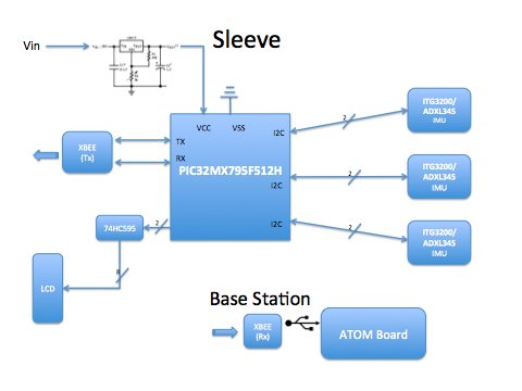
Met as team and talked about the preliminary version of the schematic, discussed possible places for decoupling capacitors and the overall structure of the power supply circuit. Made a updated block diagram.
Laid out preliminary version of the schematic, connecting all important components to the microcontroller. Presented for TCSP in class, learned that a debugging circuit is required for if we want to debug the microcontroller after we soldered it onto the PCB board. Also learned to use a voltage switch regulator instead of linear regulator to reduce power consumption.
WEEK 06 SUMMARY
Accomplishments: Laid out the preliminary schematic, including the power supply circuit, XBee, and imu interfaces. Learned in TCSP that a debugging interface is needed.
Weekly Work Total: 7 hours
Project Work Total: 40.5 hours
Week 07
Febuary 19, 2012 (1 hours):
Met as team to talk about making a more detailed schematic, and PCB design. Thought about using a LCD to display battery life and wireless signal strength. The downside of using the LCD however, is that if we choose to use a 5V LCD, then we need to somehow produce a 5V input from the 3.3V power supply.
Febuary 20, 2012 (1 hours):
Met as team to split up work for PCB design. Steve is going to implement a charge pump that will charge the 3.3V input to 5V.
Febuary 23, 2012 (1 hours):
Mike had a problem when he tried to debug the PIC32 microcontroller through the debug board. For some reaon the MPLAB could not recognize the board. Played around with the board but still couldn’t figure out why, will need to talk to Chuck or TAs about this issue
WEEK 07 SUMMARY
Accomplishments: Decided to use a charge pump to step up 3.3V input to 5V for the LCD, made custom parts library with Mike for the PCB layout.
Weekly Work Total: 6 hours
Project Work Total: 46.5 hours
Week 08
Febuary 26, 2012 (2 hours):
Started on formal design review. We broke down tasks that have to be done for the review. Found out that there are 3.3V LCDs available from Sparkfun that would fit our deisgn. In the end still decided to use the charge pump since the circuit in the schematic has already been made. Also decided to add a rocker switch to power on/off for implicity of use. Also decided to go with removable battery instead of making a charging circuit since it would be too much trouble, and we packaging design would allow us to easitly detach the battery and charge it.
Febuary 28, 2012 (1 hours):
Talked to TA about adding a bulk capacitor into our schematic. TA suggested that it should be around 50-100uF and there are one available in the lab.
Febuary 29, 2012 (5.5 hours):
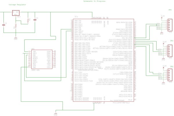
Worked on the powerpoint for the deisgn review. Updated block diagram correcting pins and removing the charge pump. We have decided to use a 3.3V LCD found on Sparkfun since then we can remove the charge pump circuit, reducing power consumption and size of the pcb board. The LCD draws less 20mA current which is not a problem since our power circuit can provide up to 3A. Added a reset button onto the schematic, however there are still problems remaining with the pcb board. Thus far the part where the reset button is added is crowded and thus it is hard to route the reset button onto the board. Also there are still some traces that are not connected or have acute angles. One pin from XBee is routed incorrectly to the microcontroller and we need to find a way to route that. Also made a project timeline for the formal review.
March 1, 2012 (2 hours):
Formal Design review. Learned several points in the review. 1) add debuggin pins into the schematic and pcb. 2) Several connections traces are still loose, and there are some acute angles. 3)Someone suggested that the user of the sleeve might be left handed. We need to take that into consideration when making data calculations and displaying image. 5)Talked about possible solutions for having variable length wires. Full Schematic
WEEK 08 SUMMARY
Accomplishments: Worked on formal design review. Finalized parts for circuit, including taking out the charge pump, using a 3.3V LCD, adding a reset button to the design.
Weekly Work Total: 9.5 hours
Project Work Total: 56 hours
Week 09
March 5, 2012 (1.5 hours):
Met as a team and broke down modules for each person to complete. Found a paper that details robot arm kinematics which should be really useful when we want to do calculations for displaying the 3D arm. The paper is called “Robot Arm Kinematics, Dynamics, and Control by C.S. George Lee”.
March 7, 2012 (2 hours):
Proof of parts briefings. Talked about how to improve the atom board’s graphic performance. Chuck said there’s not that much we can do except turning off unnecessary applications. Suggested that we should present two vesions on the final demo. One on the atom board and one on a PC. Also learned that we need to add surface aread for heat sink, and use a 16V electrolytic 100uF capacitor. Below is the PCB layout made by Harsh
March 8, 2012 (2 hours):Read more on the robot arm kinematics paper. Found we could use rotation matrices for poistion calculation. Given the rotational and translational motion data from the sensors, we could build a 4X4 rotation matrics that would give us the final position of each joints.
WEEK 09 SUMMARY
Accomplishments: Found a robot arm kinematics paper that would make it convinient for us to calculate arm position, using a rotation matrix build from sensor data. Learned how to improve the pcb board during proof of parts review, including increasing the size of the heat sink and adding bulk capacitors.
Weekly Work Total: 5.5 hours
Project Work Total: 61.5 hours
Week 10
March 12, 2012 :
Spring Break
WEEK 10 SUMMARY
Accomplishments:
Weekly Work Total: 0 hours
Project Work Total: 61.5 hours
For more detail: Augustus’s Lab Notebook