Summary of Alarm Clock using PIC16F74 microcontroller
This project is a PIC-based alarm clock inspired by the creator's son. It features two interlinked vero-board cards: a main board with a PIC16F74 microcontroller, a Dallas DS1307 real-time clock, a 5V regulator, a backup battery, and a buzzer. The PIC reads time from the RTC via bit-banged I2C to update the display and manage alarm functions, storing settings in the DS1307. A 4MHz resonator is used instead of a crystal, and connections for switches and LED displays are soldered directly due to space constraints.
Parts used in the Alarm Clock Project:
- PIC16F74 microcontroller
- Dallas DS1307 real-time clock
- 5V voltage regulator
- 3V backup battery
- Buzzer
- 4MHz resonator with built-in load capacitors
- Vero board (two interlinked cards)
- Wires for LEDs and switches
The idea for this project came from my youngest son who asked me to make him an alarm clock. I put together a simple PIC based design comprising of two interlinked vero-board cards. The design was created using New Wave Concepts’ LiveWire which allows you to simulate the effect of the signals on the components – very useful it you are new to electronics like me – If only it could simulate the PIC too!.
The larger of the two circuit boards holds the 5V power regulator, the display processor (a PIC 16F74), the real time clock (Dallas DS1307), 3V backup battery and buzzer. Click here to see a copy of the schematic for the base board in a popup window.
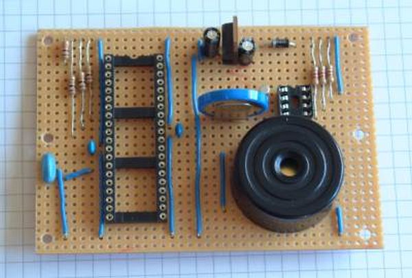
The PIC board looked like this before fitting the ICs and LED/switch wire connections. It is also missing the 1Hz signal, I2C clock and I2C data connections between the PIC and RTC chips. —I used a 4MHz resonator with built in load capacitors instead of the crystal and separate capacitors shown on the schematic. Also I added one more link wire after taking this photo to connect GND to -ve terminal of the backup battery. (The copper tracks run left-to-right on this board with cuts between the IC pins and in a couple of other strategic places.
The PIC microcontroller is programmed to read the real-time clock using I2C serial communication several times a second and update the display. It does no time keeping itself. Even the pulsing central pair of LEDs are driven by the real time clock (by means of a 1Hz output signal) and which is read by the PIC.
The PIC performs two other functions; it compares the time against the alarm settings to determine when it should go off and also handles time, date and alarm setting. The 16F74 has no EEPROM of its own so all the settings are stored in the DS1307 and read at power-on-reset. I was planning to mount connectors on the board for all the switch and display wires but in the end there wasn’t enough room so I soldered the wires directly
I ordered a 16F74 microcontroller from Farnell because it had more than enough I/O pins and supported I2C on chip. After I received the chip and read the small print in the data sheet I discovered that the SSP module was only really suitable for an I2C slave. What I really needed was a MSSP module. So my code disables the SSP module and generates the I2C master clock and data signals (on the RC3/SCL and RC4/SDA pins) using a ‘bit-banged’ approach.
For more detail: Alarm Clock using PIC16F74 microcontroller

