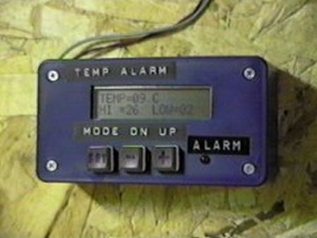
Presented is a simple temperature alarm which uses a PIC16C84 microcontroller and a 2-line LCD display. The alarm displays current temperature in both Celsius and Fahrenheit degrees and features a 3-key keypad which allows the user to set independent high and low termperature alarm points. The alarm also records the minimum and maximum temperatures encountered.
System Specifications:
The unit is designed to function (user configurable) either as a temperature alarm or a thermostat – the only difference being that with an alarm an intermittent beep is produced when a limit is exceeded.
The system samples temperature readings continually and displays the current temperature on the LCD display in both Celsius and Fahrenheit degrees. The LCD shall also display the current configuration and user parameters. User parameters include the high termperature limit, low temperature limit, and alarm mode (whether the beeper is on or off). As well, the system shall keep track of the maximum and minimum temperatures reached and display them, too, on the LCD.
The user shall have the option of setting both the high termperature limit and the low temperature limit. These limits shall be displayed in both F and C degrees and shall be set using two pushbuttons labelled UP (+) and DOWN (-). As well as limits, the user shall be able to clear the Min/Max temperatures and set the alarm mode (whether the beeper is audible or not). A red alarm LED shall light regardless of beeper status when a limit is exceeded.
All parameters including limits, min/max temperatures, and alarm (on/off) status shall be stored in non-volatile memory and shall be reloaded upon power-up.
Hardware
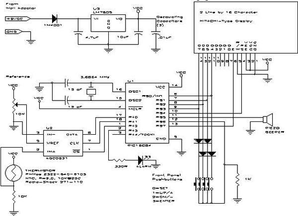
The basic system consists of a PIC16C84 MCU, a two-line 16-character LCD display, three pushbuttons to set user-configurable parameters, and an ADC0831 serial analog-to-digital converter. The LCD is an intelligent unit which displays ASCII characters. It may be used in eight-bit mode but this requires ten I/O lines on the MCU (eight for data plus register select and enable). A less-demanding four-bit interface was chosen which requires six I/O lines (four lines for data plus register select and enable). As well, to conserve I/O lines on the MCU the three pushbuttons were scanned using three of the four data lines already used for the LCD (See the schematic for details).
The ADC0831 uses a three-line SPI/Microwire interface. It is synchronous serial meaning that the MCU generates the clock and the ADC will send back the appropriate data bit (a logic high or low). This serial bitstream must be assembled by the MCU into a byte.
The thermistor used is a Philips 2322-640-63103 NTC Thermistor with an R/r ratio of 9.0 and a nominal resistance of 10K@25C. Radio Shack sells a similar unit which may be used. The thermistor is wired as one leg in a voltage divider along with a fixed 10K resistor. The voltage output of the divider is proportional to ambient temperature (although it is not a linear relationship which creates some problems for the firmware when converting to real temperatures).
The MCU is also used to drive an alarm LED (which may also be an opto-driver block if the alarm were used as a thermostat) as well as a piezo beeper to warn of over/under temperature conditions.
For more detail: A PIC-Based Temperature Alarm using PIC16C84


