Summary of Writing Robot Arm
This project implemented a 4-DOF robot arm controlled by a PIC32 to write 26 letters and 10 digits. It uses simplified inverse kinematics to map XY pen positions to four servo angles, generates four 50 Hz PWM signals (20–40% duty) to drive MG90S servos via a 3.3V-to-5V level conversion, and accepts serial commands to set characters, origin, font size, and modes. Software includes write point, drawline, and setxy functions, a character line-segment database, and motion smoothing to compensate for lack of feedback.
Parts used in the Writing Robot Arm:
- PIC32 microcontroller
- MG90S servos (4)
- 50W 5V 10A power supply
- 74LC32 OR gates (used as 3.3V to 5V converter)
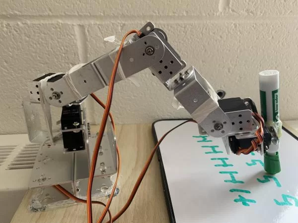
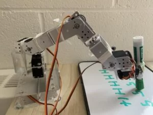
- Mechanical robot arm structure (4-DOF configuration)
- Marker/pen
- Wiring and connectors
- Timer and Output Compare hardware on PIC32 (Timer3, OC1-OC4)
Introduction
In this project, we built a writing machine using a 4-DOF robot arm. This robot arm is controlled by PIC32 and can write the 26 letters and ten numbers. Users can send instructions to the microcontroller through the serial interface to control the robot arm to write words or digits they want.
What we did:
- Developed the simplified inverse kinematics transform.
- Built the mechanical structure and the hardware of the robot arm.
- Built a character database and wrote arm control software.
- Applied the serial interface to get the user’s command.
High-level Design
- Background math
Since what we want is to control the arm write on a 2D surface, the goal is to transfer the xy axis into the PWM duty cycle of each servo. We used two steps to achieve this.
The first step is to find the relationship between the angle of each part of the robot arm and the ρ-? axis.
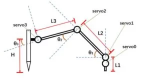
From the image above, we can see that the servo0 changes the ? in a ρ-? coordinate system while servo1,2,3 changes the ρ in the ρ-? coordinate system. Assume ? increases as rotating clockwisely.
Since we need to keep the z axis of marker constant when writing, an equation of ?1 and ?2 can be listed.
Servo3 is used to keep the marker vertical at all times. So
From the image above, we can find that
- Hardware trade offs
Due to the limitation of budget and time, this robot arm has no feedback and other sensors. We have to slow down its writing speed to make it work more stable and precisely. These are achieved by software.
Hardware
- The robot arm and the servos
The robot arm has 6 DOFs at first. We removed one and fixed one to make it a 4-DOF arm. The movements are controlled by servos. Due to the budget, the whole system had no feedback and other sensors. The servo used is MG90S. Its supply voltage is 4.8V to 6V. For each servo, the peak current while working is about 500mA, so the output of the power supply we use should be more than 6V*0.5A*4=12W. We used a 50W(5V 10A) power supply.
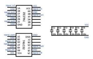
- 3.3V to 5V voltage converter
Since the amplitude of the PWM to drive this kind of servo is 4.8 to 6V and the amplitude of PWM wave generated by PIC32 is only 3.3V, a converter is needed. We used 74lc32(OR gate) to fix this problem. The schematic shows below.
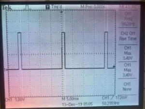
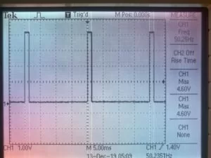
The output of the PIC32 and the output of the converter is shown below.
Software
- PWM wave generation
The robot arm has four degrees of freedom, so there are we four PWM waves to control the angle positions. Timer 3 is used to generate the wave period and OC1 – OC4 four output compare units which maps to RB7, RB8, RB2 and RB9. The generate period parameter is set to 50000, and frequency division parameter is set to 16. The PWM signal frequency is 50HZ.
The duty cycle determined the angle of servo. The relationship between duty cycle and the servo angle is shown in the table below
| Duty cycle | Angel (degree) |
|---|---|
| 20% (min) | 0 (minimum angel) |
| 30% | 90 |
| 40% (max) | 180 (maximum angel) |
The PWM generation function is in the thread: protothread_timer which enters every 1ms. In this thread, the PWM duty cycles of four PWM waves are updated based on the structure of characters to change the posture of the arm.
- Robot arm control functions
As mentioned above, the position of the pen is determined by the angles of four servos and we have already built a map table from xy coordinate of the pen to the angles of the four servo. With the duty-cycle and angle transformation table above, we wrote a function called write_xy to draw a single point on position (x, y).
However, only have the ‘write point’ function is not convenient enough to write characters. So another function called drawline is developed based on the write point function. The input of the drawline function is the xy coordinate of the start point and the end point. And it finds ten points on this line and draw a straight line in an accumulated way. The drawline function has three steps to draw a line: lift the pen from the original position, move to the start point, drop down the pen and write a line form the start point to the end point. The lifting movement can avoid draw mistakenly when we write two separated lines.
The drawline function is the foundation of the characters, we can build a character database to store the start point and end point of lines in the characters and call the drawline function to write the characters.
Another thing of writing characters is when to drop the pen down on the paper to write a character and when to move the pen above the paper in between of writing two characters. Another function called setxy is applied on this situation. Setxy function has two parameters, the first one is the target coordinate, the other one is the state of the arm when it reaches that position. The state of the arm are dropping the pen down or uplifting the pen.
Since there is no feedback or other sensors to control the speed of the servos, in software, we reduce the PWM duty cycle smoothly to avoid moving arm so fast and braking the mechanical structure of the arm.
- Characters database
The basic idea of writing characters on the paper is that we store the line information of 10 digits (0 – 9) and 26 letters (A – Z) as a hash table, when we receive a character input command from serial we check the table then send the coordinate information to the drawline function.For example, the data structure of letter ‘A’ can be: [(1,2,1 + font_size * 2,2 – font_size), (1,2,1 + font_size + 2,2 + font_size), (2,1.5,2,1.5 + font_size)] which means the start points and the end points of 3 different lines and the font_size parameter determined the size of the character. The example below shows characters ‘A’ when font_size = 1.
One thing needs to clarify is that the numbers in the point coordinate above is not the absolute position of the points but the relative position according to original point (0, 0). In fact the original point is the desired position where we want to write this character, and based on this position, we add relative offset and get the actual position of the line points.
- Serial communication
The writing arm is controlled by the input instruction form serial command line. From the serial, users can set characters they want, the original x y coordinate of the characters, font size of the characters. In addition to those basic information of the characters, there are three modes of the format. Basic mode is for writing a single character, it will reset the original point coordinate to (0, 0) every time the arm finish writing a character. Line mode is for writing a word (with multiple characters). In this mode after writing a character, the arm will automatically find original point coordinate of the next character without overlapping with the previous one. The third mode is the test mode, which is designed for this course. The arm will write the course number “ECE4760” automatically without user input those characters.
Result and Conclusions
- PWM wave
The PWM is 50HZ with duty cycle from 20% to 40%. And the hardware increase the amplitude of the PWM output from PIC32 to 5V. The following image is the results of the amplified PWM.
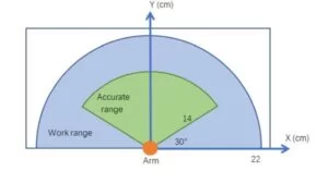
- Accuracy of writing
Because of the imprecision of the mechanical structure and approximation of the servo angles the accuracy of writing varies related to the distance from the robot arm. The figure below shows the range where the arm can reach and the accuracy distribution in the work range.
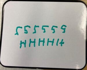
The figure below are character ‘5’ and ‘H’ written in the line mode to test the variance of accuracy of different x y coordinate.
- Example
The figure below are character ‘5’ in different font size and the test mode result.
Commented Code
-
- You can find the whole code here, there are three important writing functions.
                    // set the pen to x y positon
                    void setxy(double x, double y, int down){
                        int a,b;
                        int i;
                        a = getsita12(x,y);
                        b = getsita0(x,y);
                        SetDCOC2PWM(angle1[a]-500);                                             //servo1
                        delay_ms(50);
                        SetDCOC3PWM(angle0[b]);                                                 //servo0
                        SetDCOC1PWM(angle2[a]);                                                //servo2
                        SetDCOC4PWM(angle3[a]+300);                                            //servo3
                        delay_ms(50);
                        if(down == 1){                                                         //put down the pen smmothly
                            for(i = 0;i <= 24; i++){
                                SetDCOC2PWM(angle1[a]-500+20*i);                               //servo1
                                delay_ms(50);
                            }
                        }
                        delay_ms(1000);
                    }
                    // write a single point at (x, y)
                    void writexy(double x, double y){
                        int a,b;
                        a = getsita12(x,y);
                        b = getsita0(x,y);
                        SetDCOC3PWM(angle0[b]);                                                //servo0
                        SetDCOC2PWM(angle1[a]);                                                //servo1
                        SetDCOC1PWM(angle2[a]);                                                //servo2
                        SetDCOC4PWM(angle3[a]+300);                                            //servo3
                        delay_ms(100);
                    }
                    // draw a straight line accumulatedly
                    void drawline(double x1, double y1, double x2, double y2){
                        double stepx,stepy;
                        int i;
                        stepx = (x2-x1)/10.0;                                                  // calculate the step size
                        stepy = (y2-y1)/10.0;
                        writexy(x1,y1);
                        for(i=0;i<=10;i++){
                            x1 = x1 + stepx;
                            y1 = y1 + stepy;
                            writexy(x1,y1);
                        }

                    }
Source: Writing Robot Arm
- How does the system convert XY coordinates to servo signals?
The system uses a simplified inverse kinematics transform and a lookup map from XY to four servo angles, then converts angles to PWM duty cycles. - Can the robot write full letters and numbers?
Yes, it can write 26 letters and 10 digits using a character database of line segments. - What PWM frequency and duty cycle range are used for the servos?
The PWM frequency is 50 Hz with duty cycles from 20% (0 degree) to 40% (180 degrees). - How does the robot avoid drawing between separate strokes?
The drawline function lifts the pen before moving, then drops it to write, using setxy to control pen up or down states. - Does the system include feedback sensors?
No, due to budget and time constraints the system has no feedback or other sensors. - How are multiple characters or words handled?
There is a line mode where after writing a character the arm computes the next original point to avoid overlap; basic mode writes single characters resetting origin, and test mode writes a preset string. - How is 3.3V PIC32 PWM output adapted to servo voltage?
A 74LC32-based level conversion circuit is used to increase PWM amplitude to the 4.8–6V range required by the servos. - What software functions implement motion and drawing?
Key functions are setxy to move and set pen state, writexy to write a single point, and drawline to draw straight lines by stepping between points.