Summary of Wireless servo controller II
Summary: This article shows how to control a model servo by reading a potentiometer via a TR module ADC, converting the 10-bit ADC to 8-bit, scaling the value, and sending it wirelessly in a 2-byte RF packet to drive the servo. It adapts an ADC sensor example and includes code snippets for periodic reading, conversion, and RF transmission.
Parts used in the Wireless servo controller II:
- Potentiometer
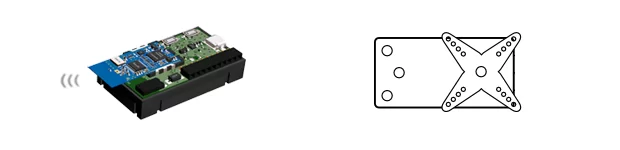
- TR module with ADC (sensor module)
- Microcontroller (running the ADC example code)
- Modeller servo
- RF transmitter/receiver pair (RFTXpacket function on transmitter side)
- Power supply (for microcontroller, TR module, and servo)
- Wires and connectors
We described simple method, how to drive modellers servo. Today, we are going to try to drive this servo from potentiometer connected to TR module ADC. It is reaction to forum thread where is discussion about airplane model control possibility.
We are going to use redesigned ADC usage example (sensor module source code) in this way:
while(1)
	{
		//clrwdt();
		waitDelay(5);
		ReadAnalogInput();

		voltage = ADC_result / 4;    //10b to 8b
		voltage = voltage * 181;     // 181/256 = aprox. 0.707031
		bufferRF[0] = 'S';
		bufferRF[1] = voltage.high8 + 70;

		PIN  = 0;
		DLEN = 2;
		RFTXpacket();
	}
For more detail: Wireless servo controller II
- How is the ADC reading converted from 10-bit to 8-bit?
The code divides ADC_result by 4 to convert 10-bit to 8-bit. - How is the ADC value scaled before transmission?
The 8-bit value is multiplied by 181 to approximate scaling by 0.707031 (181/256). - What data is sent in the RF packet to control the servo?
A two-byte packet is sent: bufferRF[0] = 'S' and bufferRF[1] = the scaled voltage high8 value plus 70. - How often is the ADC read and transmitted?
The loop waits delay(5) between iterations and then reads and transmits, so it repeats after each waitDelay(5) plus processing time. - Which function handles sending the RF packet?
The function RFTXpacket() is called to transmit the packet. - What part of the code forms the packet length?
DLEN is set to 2 to indicate a two-byte packet. - How is the packet buffer prepared before transmission?
bufferRF[0] is set to 'S' and bufferRF[1] is set to voltage.high8 + 70, then PIN is cleared and DLEN set before calling RFTXpacket(). - What example was adapted for this project?
The redesigned ADC usage example (sensor module source code) was adapted for this project.