Summary of Voltmeter and Ammeter using PIC Microcontroller
This article details a project to build a voltmeter and ammeter using a PIC16F877A microcontroller with an ADC module. The circuit measures 0–30V and current by scaling voltages via a divider and a shunt resistor, displaying results on an LCD. It explains the 10-bit ADC resolution, calculation formulas for voltage and current, and software conversion methods.
Parts used in Voltmeter and Ammeter using PIC Microcontroller:
- PIC16F877A Microcontroller
- LCD Display
- Voltage Divider (20K ohm and 120K ohm resistors)
- Shunt Resistor (.47 ohm special resistor)
- Fuse
- 100K ohm resistor
- 5.1V Zener Diode
Voltmeter and Ammeter can be easily made using PIC Microcontroller having ADC (Analog to Digital Converter). I am using PIC16F877A and the result is displayed on an LCD Display. PIC16F877A is enough if you do this project only for testing purposes. I suggest to use PIC with low pin numbers and multiplexed 7 segment display if you wish to use this as your measuring instrument.
If you don’t know the basis of PIC ADC and LCD Interfacing please read the following articles.
ADC module of PIC Microcontroller converts the Signals on its analog pin to 10 bit binary data and it has software selectable high and low voltage reference input to some combination of VDD, VSS, RA2 and RA3. The analog input to PIC is limited to VSS and VDD voltages (0 – 5V) of PIC.
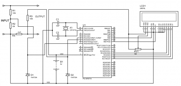
This circuit is designed to measure 0 to 30V. So we will map 0 to 30V to 0 to 5V by using a voltage divider. Current through a circuit can be measured by introducing a 1 ohm resistor and measuring the voltage across it. To minimize the path resistance we will use .47 ohm special resistor with fuse (shown in figure) and current is calculated. Voltage and Current Sampling circuit is shown below. When the Input voltage is 30V (max) the voltage across 20K ohm resistor becomes 5V which is feedback to the analog pin RA2 of the PIC Microcontroller.
The voltage across .47 ohm resistor is also feedback to the analog pin RA3 via 100K ohm resistor. 5.1V Zener Diode is added in parallel to these analog input pins to protect PIC from over voltages.
The ADC module of PIC converts analog input to 10 bit digital number. We want to convert this digital to corresponding voltage in decimal.
- 0v = 0 0 0 0
- 5v = 1 1 1 1
Resolution = (Vref+ – Vref-)/(1024-1) (as it is 10 bit ADC)
= 5/1023
= 4.887 mV
Thus it means that for a change in 4.887mV, the binary output changes by 1.
So voltage input to the analog pin of PIC can be calculated as follows…
v = ADC_Read(2);  // ADC value of channel 2 (voltage)
i = ADC_Read(3);  // ADC value of channel 3 (current)
V = v*4.89;       // Converting ADC value to mV
I = i*4.89;       // Converting ADC value to mV
By using values V and I we can calculate the Input Voltage and Current across the Load (Connected across Output terminals).
Voltage across 20K resistor = V
Current through 20K = V/20K
Input Voltage = Current through 20K * 120K (Current flowing to PIC can be neglected)
Thus,
V = (V/20)*120;
Voltage across 0.47 ohm resistor = V
Current through Load = Current through 0.47 ohm resistor = V/0.47
Thus,
I = I/0.47;
To display the results in LCD Display we need to convert these readings into string, we use the user defined function look() for it. It converts each digit in the reading to corresponding character (see the source code).
Circuit Diagram
For more detail: Voltmeter and Ammeter using PIC Microcontroller
- How can a voltmeter and ammeter be made?
They can be easily made using a PIC Microcontroller having an ADC module. - What is the maximum input voltage this circuit is designed to measure?
The circuit is designed to measure 0 to 30V. - How is the analog signal converted to digital data?
The ADC module converts signals on its analog pin to 10 bit binary data. - What component protects the PIC from over voltages?
A 5.1V Zener Diode is added in parallel to the analog input pins. - How is current measured in this project?
Current is measured by introducing a .47 ohm resistor and measuring the voltage across it. - What is the resolution of the 10 bit ADC used?
The resolution is calculated as 4.887 mV per change in output. - Which analog pins are used for voltage and current sampling?
Voltage is fed to RA2 and current is fed to RA3. - How are the readings displayed on the screen?
Readings are converted into strings using a user defined function called look() and shown on an LCD Display.