Summary of Voltage programmable simple logic device using PIC12F675
This article describes a PIC12F675-based project that functions as a configurable 2-input logic gate or square wave generator. The device determines its logic function (AND, OR, XOR, NAND, NOR, XNOR) via an analog voltage on GPIO4 at reset, or retrieves a saved setting from EEPROM if GPIO5 is high. Unused voltage levels enable two square wave modes with selectable frequencies based on input pins. The author demonstrates the concept by building a D-type flip-flop using five such logic elements and one clock generator.
Parts used in Voltage Programmable Simple Logic Device:
- PIC12F675 microcontroller
- Analog-to-Digital Converter (ADC)
- GPIO4 pin (Function Select Input)
- GPIO5 pin (Power-up Mode Select)
- EEPROM memory storage
- D-type flip-flop circuit components
- Square wave generator circuit
- Pushbutton switch (Data Input)
- Internal weak pull-up resistors
- External resistor network (10K, 4.7K, 2.2K, 8.2 ohm, 6.8 ohm)
Description
Here’s another daft yet interesting PIC12F675 idea I came up with. When I wanted to show someone how logic gates worked I could only find a NAND gate which wasn’t very handy for demonstrating AND’s OR’s, NOR’s and ExOR’s. I also wanted to have a play with the A/D converter on the 12F675 so I came up with the idea of a PIC that could function as a single 2-input logic element.
The logic function is determined by an analogue voltage applied to the GPIO4 pin when the device is first reset, it isn’t sampled again after this so logic can’t be changed on the fly. The 3 MSBs of the A/D conversion give eight distinct voltage levels that map to specific logic functions. Six functions have been implemented; these are 2 input AND, OR and EXOR gates and their negated equivalents.
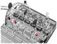
Just to prove the concept, here is a ‘D’ type flip flop (PIC Flop:-) I built out of five 12F675 Logic Elements operating as NAND gates. The sixth device is configured to operate in square wave mode to provide a clock input to the flip-flop for testing. The small pushbutton provides the ‘data’ input.
Square wave generator
With 8 analogue voltage levels and only six logic functions, this left two unused functions so these have been used to provide a square wave generator. There are two modes, fast and slow selected by the voltage on the function select pin. Once selected the program reads the data on inputs A and B and sets the frequency on the output pin according to the table below.
This is read each cycle so the frequency can be adjusted during operation.
B A Freq’
0 0 1KHz, 2.5Hz
0 1 100Hz, 1Hz (1s)
1 0 50Hz, 0.5Hz (2s)
1 1 25Hz, 0.25Hz (4s)
Selecting the Function
When the device is first powered up it reads the logic level on GPIO5. If the input is low, the analogue voltage on GPIO4 is sensed and the logic function determined as described above. The function selected is then saved to EEPROM.
If the GPIO5 input is high when the device is powered up, the previously saved function is read from the EEPROM and used. In this case the analogue voltage on GPIO4 is ignored. This allows the function that the PIC will perform to be selected once and saved so it can be used repeatedly without having to set it each time the PIC is powered on.
| Function value | Function | Voltage select |
| 0 | AND | GP4-Vss |
| 1 | OR | Vdd-10K-GP4-2.2K-Vss |
| 2 | XOR | Vdd-10K-GP4-4.7K-Vss |
| 3 | Square Wave fast | Vdd-10K-GP4-8.2-Vss |
| 4 | NAND | Vdd-6.8-GP4-10K-Vss |
| 5 | NOR | Vdd-4.7K-GP4-10K-Vss |
| 6 | XNOR | Vdd-2.2K-GP4-10K-Vss |
| 7 | Square Wave slow | Vdd-10K-GP4 |
Floating Inputs
The inputs on pins GPIO0, 1 and 5 have the weak internal pull-up feature enabled so no external pull-up resistors are required.
Selecting function during device programming
If your programmer supports writing to the EEPROM at program time, you can set up the function when the code is programmed into the PIC. This avoids the need to ‘user program’ the function with an analogue voltage on first use. To do this you need to set the first three memory locations in the EEPROM as follows: (see Source Code)
| Address 00 | function from 0x00 thru 0x07 (see table above) |
| Address 01 | 0x81 – validation byte |
| Address 02 | 0x69 – validation byte |
If the validation bytes are not correct, the EEPROM will be initialised and the function set to 0
Code and schematics
This code is written to work on a 12F675 device. The HEX file below is assembled for and has been tested with the 12F675. It should work on a 12F683 too but I haven’t tried it. This code won’t work with a 12F629 because it doesn’t have the ADC feature.
-
Hex(V2)
 file ready to program (right-click Save As)
For more detail: Voltage programmable simple logic device using PIC12F675
-
How is the logic function determined?
The function is determined by an analogue voltage applied to the GPIO4 pin when the device is first reset. -
Can the logic function be changed while running?
No, the voltage is not sampled after reset, so logic cannot be changed on the fly. -
What happens if GPIO5 is high during power up?
The previously saved function is read from the EEPROM, and the analogue voltage on GPIO4 is ignored. -
Which logic functions are implemented?
Six functions are implemented: AND, OR, EXOR, NAND, NOR, and XNOR. -
How does the square wave generator work?
It uses unused voltage levels for fast and slow modes, adjusting frequency based on data inputs A and B. -
Do I need external pull-up resistors for floating inputs?
No, the internal weak pull-up feature is enabled for GPIO0, GPIO1, and GPIO5. -
Can I set the function during programming?
Yes, you can write specific values to the first three EEPROM locations to set the function at program time. -
Is this code compatible with the PIC12F629?
No, it will not work because the PIC12F629 lacks the ADC feature required for this design.