
Summary of Voice Modulator (Sound Effects)
This project is a voice modulator using the HT8950 chip to generate vibrato and robot sound effects. It features an 8kHz sampling rate, built-in microphone amplifier, and SRAM. Users can select effects via pins or buttons and adjust volume through seven steps. The circuit includes an LM386 audio amplifier, LED indicators for power and voice level, and operates on 6V DC with an 8Ω speaker output.
Parts used in the Voice Modulator:
- HT8950 Chip
- LM386 Audio Amplifier
- Electret Condenser Microphone (MIC1)
- Speaker (LS1) 8 Ω / 0.5 W
- LED Indicators
- ON/OFF Slide Switch
- PBT Power Battery Terminal Connectors
- PCB Board
- Volume Control Preset
Description
This project provides two special effects: vibrato and robot. The vibrato effect is generated by alternating the frequency of an input signal up and down at a rate of 8Hz. The robot function, on the other hand, converts an input voice into a robot voice. Both effects can be selected depending on which pin is triggered, either ROB or VIB. For the output frequency level shifting, the chips provide seven steps which can be selected from the two groups of pins namely, SW0, SW1 and SW2 for electronic direct selection and ROB, TGD, TGU and VIB for push button selection.
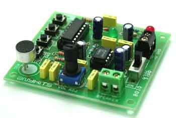
The HT8950 include a built-in microphone amplifier with an internal bias, an 8-bit A/D converter, a built-in SRAM as well as a current output type 8-bit D/A converter. The 8-bit A/D and D/A converters with a sampling rate of 8kHz ensures a high quality and high S/N ratio output voice. The chips provide an LED indicator which flashes in accordance with the volume of the input voices.
Specifications:
Input – 6 VDC @ 300 mA
Output – Speaker, 8 Ω / 0.5 W
7 Step level shifting (Volume Control) SW3 (TGU) and SW4 (TGD)
SW2 – Vibrato mode, SW5 – robot mode
LED to display the voice level input
ON/OFF slide switch for power supply
Audio amplifier type LM386 with volume control preset
PBT (Power Battery Terminal) connectors for supply voltage and speaker output
Power-On LED indicator
PCB dimensions 63 mm x 68 mm
CN1 – 6 VDC Supply Input
MIC1 – Electret Condenser Microphone
LS1 – Speaker
For more detail: Voice Modulator (Sound Effects)
-
What special effects does this project provide?
The project provides two special effects: vibrato and robot. -
How is the vibrato effect generated?
The vibrato effect is generated by alternating the frequency of an input signal up and down at a rate of 8Hz. -
Which pins trigger the different modes?
The ROB pin triggers the robot function and the VIB pin triggers the vibrato mode. -
How many steps are available for output frequency level shifting?
The chips provide seven steps for output frequency level shifting. -
What is the sampling rate of the A/D and D/A converters?
The 8-bit A/D and D/A converters operate with a sampling rate of 8kHz. -
What type of microphone is used in the circuit?
An Electret Condenser Microphone is used as MIC1. -
How is the power supply connected?
Power is supplied via PBT connectors with a requirement of 6 VDC @ 300 mA. -
What does the LED indicator display?
An LED flashes in accordance with the volume of the input voices.

