Summary of USB Reprogrammable iButton door lock
This article details a DIY project to build a secure, reprogrammable door lock using Dallas iButtons. The system allows up to 80 unique keys and features a USB programmer for easy key updates without disassembly. It supports various electronic door releases operating between 5-30V AC or DC.
Parts used in the Reprogrammable iButton Door Lock:
- Bridge Rectifier (rapid# 47-3202)
- 5v 7805 voltage regulator (rapid# 47-3313)
- SIL relay (rapid# 60-0670)
- 100uf capacitor
- 470uf capacitor
- 220f capacitor
- 2x 1k resistors
- 1x 4k7 resistor
- 16f628 PIC microcontroller
- 24LC04 4k EEPROM
- 8pin DIL holder
- 18pin DIL holder
- DPDT mini switch (rapid# 76-0670)
- 3pin header (rapid# 22-0515)
- Jumper (rapid# 77-0237)
- 2x 2pin terminal blocks (rapid# 21-1700)
- Electronic door release
- iButton probe with BiColour LED (MBL part# hc00039)
- DS1990A iButtons (1-80 units)
- USB Programmer components: 18f2550 PIC micro, 20MHz XTAL, capacitors, resistors, LED, USB B-socket, iButton holder probe DS1402, and DS1973 iButton
iButtons are small button like casings that communicate with only 2 wires. They are incredibly robust and all have a unique serial number which is hardware written into the device and never repeated. They are cheap (about 1 Pound / 1,50 Euro/ $2)
This serial number allows the keys to be truly unique and thus are effectively secure. I have seen them used:
>as the till logon device at bars
>in securicor money cases
>computer logins
>as secure dongles used with expensive software.
>…as door locks!
The problem with using them for the beginner, is that you have to be able to program hardware to read them and if you loose the key, the locking device is useless!
This Instructable shows you how to build a lock, and a USB programmer that enables you to write new keys to the lock in seconds, without dismantling the unit. Making the lock completely secure and updatable for up to 80 keys at a time. The lock can work on between 5-30V AC or DC and so is incredibly flexible; designed to work on the same voltage as your electronic door release – you can buy the cheapest or most expensive one you find, Fail-Locked or Fail-Unlocked, AC or DC, 12V or 24V.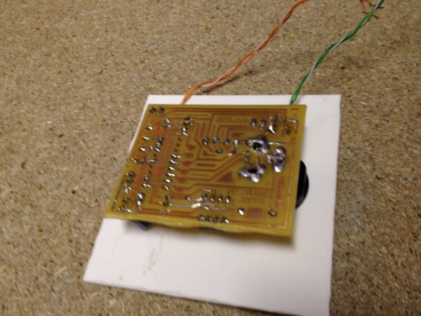
What you will need:
>Components (see next)
>PIC programmer
>Electronic door release.
>PCB making equipment (if you want to make it look puurdy)
NOTE!!!
This is an old instructable that I haven’t uploaded for some reason. If you have trouble building it, email me and I will happily help – however, I can’t guarantee I’ve made it as simple as possible – sorry – hopefully it’ll give inspiration if nothing else.
Step 1: The Process
Firstly you’ll need to decide which type of lock you need.
FAIL SAFE/UNLOCKED remain open when the unit looses power. This would generally be used if the door nbeeds to be accessable in the event of a power failure – e.g Fire
FAIL SECURE/LOCKED remain locked unless power is applied to the lock. These would be more appropriate when using a traditional door entry system, having the door traditionally locked at all times, unless power is applied.
Below is a flow chart to show how the device operates.
Simply, if you enter a key, the microprocessor firsts checks to see if it’s a programming key, or it’s an access key.
If it’s an [iButton] access key, the microprocessor checks against the list of known keys stored in it’s EEPROM (memory), if it finds it, it lets you in. Otherwise it will send a red-light to say that no access is granted.
If it’s a reprogrammable key of any type (e.g. an iButton with a new list of keys to store on the internal EEPROM). It will check if the ibutton is allowed to re-program the internal EEPROM but checking it’s authentication code. (This is programmed into the iButton by the USB programmer and this you can’t change – see last page for info).
If the iButton is allowed to program the internal EEPROM, the LED will flash Green/Orange and then microprocessor will pull all the key-codes off the iButton and store them to it’s internal EEPROM. This will cause the LED to flicker and could take up to 20 seconds – do not remove the key while this is happening. The LEDS will then pulse green to indicate the programming is over – now remove the iButton.
Step 2: The components
I’m going to give the parts list and the Rapid Electronics ( http://www.rapidonline.com ) part number so you can source your own supplier – although rapid is pretty good!
Heres the parts listDoor Lock
1x Bridge Rectifier (rapid# 47-3202)
1x 5v 7805 voltage regulator (rapid# 47-3313)
1x SIL relay (rapid# 60-0670)
1x 100uf cap (rapid# 10-3260)
1x 470uf cap (rapid# 11-0275)
1x 220f cap (rapid# 11-0260)
2x 1k resistor
1x 4k7 resistor
1x 16f628 PIC micro
1x 24LC04 4k eeprom (rapid# 22-0170)
1x 8pin dil holder
1x 18pin dil holder
1x DPDT mini switch (rapid# 76-0220)
1x 3pin header (rapid# 22-0515)
1x jumper (rapid# 77-0237)
2x 2pin terminal block (rapid# 21-1700)
1x Electronic release ( http://www.directlocks.co.uk )
1x iButton probe with BiColour LED (MBL)(part# hc00039 http://www.homechip.com )
1-80x DS1990A iButtons ( http://www.homechip.com )
The USB programmer
1x 18f2550 PIC micro
1x 20MHz XTAL
2x 22pf caps (ceramic disc)
1x 220nf cap
1x 1k res
1x LED (any colour)
1x USB B-socket
1x iButton holder probe DS1402 (any will do) ( http://www.homechip.com )
1x DS1973 iButton ( http://www.homechip.com )
Some of the iButton hardware or buttons may be obtained free by ordering samples from http://www.ibutton.com (direct from maxim).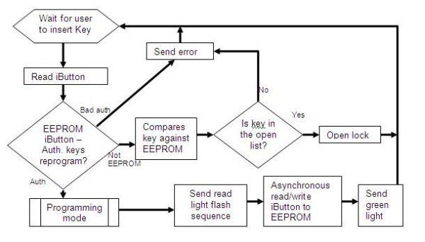
Step 3: Schematic and PCB for lock
Below is the schematic, the PCB and the final example photo of the lock. For a printable PCB layout, see downloads.
For a high res version of the Schematic, click the i and download the file (14kb).
PCB layouts are available on the download page.
Step 4: Schematic, PCB and photo of the programmer
-
How does the device distinguish between an access key and a programming key?
The microprocessor first checks if the inserted key is a programming key or an access key to determine the next action. -
What happens if an invalid access key is presented?
If the key is not found in the stored list of known keys, the device sends a red light indicating no access is granted. -
Can this lock be used during a power failure?
Yes, by selecting a Fail Safe/Unlocked model which remains open when power is lost, suitable for fire safety scenarios. -
How many keys can the lock store at one time?
The lock is designed to work with and store up to 80 keys at a time. -
What voltage range does the lock support?
The unit operates on a flexible voltage range of between 5-30V AC or DC. -
How long does the programming process take?
Programming the internal EEPROM can take up to 20 seconds, indicated by flickering LEDs. -
Is it necessary to dismantle the unit to update keys?
No, the USB programmer enables writing new keys to the lock in seconds without dismantling the unit. -
Where can I obtain free iButton hardware samples?
Some iButton hardware or buttons may be obtained free by ordering samples from http://www.ibutton.com.