Table of Contents
- Introduction
- 1 What is a Microcontroller?
- 2 Why are Microcontrollers used?
- 2 Getting started
- 1 Parts list and vendors
- 2 Connecting the equipment
- 3 PIC16fF877 Microcontroller
- 1 Flash PIC development board
- 2 CCS PIC-C compiler
- 3 In Circuit Debugger/Programmer (ICD-S)
- 4 Embedded C Programming and the Microchip PIC
- 4 Experiments on PIC16F877
- 1 LED
- 2 Dip Switch
- 3 ADC Temperature Measurement
- 4 Open Loop and Closed Loop Temperature Control
- 5 Where do we go from here?
- Introduction
This tutorial is to introduce the microcontroller technolgy the capabilities and the specifications of a commonly used Microcontroller Microchip PIC16F877 and describe the experiments conducted using the Development board Flash PIC development board which accomodates this microcontroller.
- 1. What is a microcontroller?
A microcontroller is a compact standalone computer, optimized for control applications. Entire processor, memory and the I/O interfaces are located on a single piece of silicon so, it takes less time to read and write to extrernal devices.
- 2. Why are microcontrollers used?
Following are the reasons why microcontrollers are incorporated in control systems:
- Cost: Microcontrollers with the supplemantary circuit components are much cheaper than a computer with an analog and digital I/O
- Size and Weight: Microcontrollers are compact and light compared to computers
- Simple applications: If the application requires very few number of I/O and the code is relatively small, which do not require extended amount of memory and a simple LCD display is sufficient as a user interface, a microcontroller would be suitable for this application.
- Reliability: Since the architecture is much simpler than a computer it is less likely to fail.
- Speed: All the components on the microcontroller are located on a singe piece of silicon. Hence, the applications run much faster than it does on a computer
Note: It is assumed that the user has the following common electrical equipment: 1×8 pin ribbon cable, alligator clips, soldering iron and solder.
- 2. Connecting the equipment
- Powering up the PIC Development Board
The PIC16F877 chip has to be powered at all times when its being programmed and running an application.
- Cut the connector off the DC end of the 12VDC adapter and strip the wire ends.
- Determine the + and – wire leads using a voltmeter.
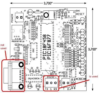
- Apply the 12VDC to the board by connecting the 12VDC adapter to + and – pins of J2 of Flash PIC Development Board. See Figure2.2-1
Caution: Make sure you wire the – and + ends of the adapter of the to the right pins of Jumper 2. Do not plug the adapter to 110V/AC outlet before you wire the power to the board. In order to avoid cheking the leads with a voltmeter everytime, its always a good practice to label the leads for future reference.
- Plug the adapter to the 110V/AC outlet.
- Observe the green LED D9 illuminating and rest of the LEDs flashing in order.
b.Connecting the Flash PIC Development Board to a PC through ICD-S:
After we put power on the FlashPIC development board, now we are ready to program the PIC16F877 chip.
- Connect the ICD-S to the computer using the RS-232 cable, which came with the ICD-S.
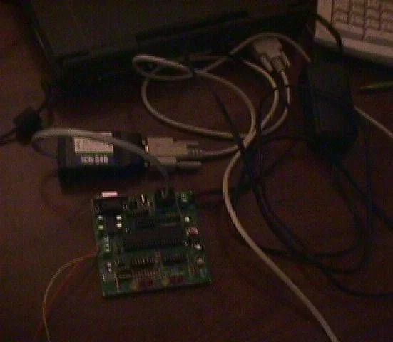
- Conncect the ICD-S to the developmet board using the phone jack. (See Figure2.2-2)
Figure2.2-2 Connecting the ICD-S, PC, and the FlashPIC-Development Board
- Coding,Compiling and Transfering the .hex files to the chip
Now that we have our hardware setup, we are ready to write the code and transfer the .hex files to the PIC16F877.
- Install the CCS compiler demo version, which came with the reference book ”Embedded C Programming and the Microchip PIC” to your computer
- Insall the ICD software which came with the ICD-S unit.
- Start the CCS compiler.
- Go to menu path: Options>Debugger/Programmer
- Change the to the path of Icd.exe. (See Figure2.2-3)This would enable starting the ICD-S software via toolbar button.
Figure-2.2-3 Device Debugger/Programmer Options Menu
- The software setup is complete. We can type the source code and compile it and transfer the file to the PIC chip as illustrated in Figure2.0-3. After single clicking the “compile” command button on the toolbar and generating the .hex file, we can single click the “program chip” command button. These coomand buttons are illustrated in Figure 2.2-4.
Figure2.2-4 The CCS Compiler
- After the “program chip” command button is pressed the ICD V2.7 program is initiated. First we check the RS-232 communications, the ICD-S and the PIC16F877 by using the following command buttons respectively: “Check COMM”, “Test ICD”, “Test Target”. If all of them check to be OK, now we can browse and transfer the .hex file to the chip by using “Download to target Command button”. After the .hex file is transferred, now we can run the software and test its functionality by clicking on “Run Program” command button. (Figure2.2-4)
- Since the software is tested now the ICD-S can be disconnected and the Development board can be powered up and the .hex file can be run without being connected to the computer.
Figure2.2-5 ICD Control Program
- PIC16F877 Microcontroller
In this section, properties of PIC16F877 microcontroller,CCS compiler, ICD-S, the reference book “Embedded C programming and the microchip PIC” are briefly explained to give a general idea; it may seem confusing for a first time reader who is not familiar to microcontrollers technology or C programming. However, as the funtionality of the components such as timers, A/D converters, I/O Ports are explained in detail in Section 3 as they are being used in the experiments, the fundemental concepts would be better understood and, the reader can flashback to this section to view the schematics and the specifications.
PIC16F877 is one of the most commonly used microcontroller especially in automotive, industrial, appliances and consumer applications. In Figure –1, the block diagram of the PIC16F877 is illustrated.
The core features of PIC16F877 are:
- High performance RISC CPU
- Only 35 single word instructions to learn
- All single cycle instructions except for program
branches which are two cycle
- Operating speed: DC – 20 MHz clock input
DC – 200 ns instruction cycle
- Up to 8K x 14 words of FLASH Program Memory,
Up to 368 x 8 bytes of Data Memory (RAM)
Up to 256 x 8 bytes of EEPROM Data Memory
- Pinout compatible to the PIC16C73B/74B/76/77
- Interrupt capability (up to 14 sources)
- Eight level deep hardware stack
- Direct, indirect and relative addressing modes
- Power-on Reset (POR)
- Power-up Timer (PWRT) and
Oscillator Start-up Timer (OST)
- Watchdog Timer (WDT) with its own on-chip RC
oscillator for reliable operation
- Programmable code protection
- Power saving SLEEP mode
- Selectable oscillator options
- Low power, high speed CMOS FLASH/EEPROM
technology
- Fully static design
- In-Circuit Serial Programming. (ICSP) via two
pins
- Single 5V In-Circuit Serial Programming capability
- In-Circuit Debugging via two pins
- Processor read/write access to program memory
- Wide operating voltage range: 2.0V to 5.5V
- High Sink/Source Current: 25 mA
- Commercial, Industrial and Extended temperature
ranges
- Low-power consumption:
– < 0.6 mA typical @ 3V, 4 MHz
– 20 μA typical @ 3V, 32 kHz
- – < 1 μA typical standby current
The peripheral features of the PIC16F877 are:
- Timer0: 8-bit timer/counter with 8-bit prescaler
- Timer1: 16-bit timer/counter with prescaler,
can be incremented during SLEEP via external
crystal/clock
- Timer2: 8-bit timer/counter with 8-bit period
register, prescaler and postscaler
- Two Capture, Compare, PWM modules
Capture is 16-bit, max. resolution is 12.5 ns
– Compare is 16-bit, max. resolution is 200 ns
– PWM max. resolution is 10-bit
- 10-bit multi-channel Analog-to-Digital converter
- Synchronous Serial Port (SSP) with SPI. (Master
mode) and I2C. (Master/Slave)
- Universal Synchronous Asynchronous Receiver
Transmitter (USART/SCI) with 9-bit address
detection
- Parallel Slave Port (PSP) 8-bits wide, with
external RD, WR and CS controls (40/44-pin only)
- Brown-out detection circuitry for
Brown-out Reset (BOR)
The Pinouts of the PIC16F877 is given in Figure 3.0-2
Figure 3.0-2 Pin diagram of PIC16F877
- 1. Flash PIC development board
Usually, a microcontroller by itself is not sufficient to perform the intended tasks. For instance, an oscillator chip is necessary to time the programmed instructions. In order to investigate the capabilities or to test a given microcontroller, obviously it is vital to build the proper circuitary. Example: potentiometer and a power supply to simulate analog inputs or LEDs to simulate the digital outputs. Hence, some hardware and sofware vendors provide the microcontroller with the supplemantary circuit elements on the same breadboard. These boards are called Development Boards. One can also build a development board himself/herself if he/she is willing to go through the painsaking process of building the circuit.
The parts list and the vendor list is given in Table-2.1.1
| Description | Vendor | Part No. | Price | Qty. |
| FlashPIC-Development Board | PRLLC | FlashPIC-Dev | 45.00$ | 1 |
| CCS ICD-S debugger/
programmer |
PRLLC | ICD-S | 75.00$ | 1 |
| Embedded C Programming and the Microchip PIC
Richard H. Barnett, Larry D. O’Cull, Sarah A. Cox ISBN: 1401837484 |
Amazon.com | N/A | 57.70$ | 1 |
| 12VDC adapter | Radioshack | 273-1776 | 16.99$ | 1 |
| 8 position dip switch | Jameco | 38842 | 0.89$ | 1 |
| Multipurpose PC Board | Radioshack | 276-150 | $1.69 | 1 |
| LM35CZ Linear Series | Jameco | 107107 | $5.79 | 1 |
| Plastic Sphere | Bubblegum machine | |||
| DAC-0832 8 bit DAC | Jameco | 128186 | 3.95 | 1 |
| LF353 Op-Amp | Jameco | 22939 | $.39 | 1 |
| 10Kohm Resistor | Radioshack | 271-1335 | $.99 | 1 |
| 20Kohm Resistor | Radioshack | 271-0265 | $.99 | 2 |
| 10ohm 10W Resistor | Radioshack | 271-132 | $1.69 | 1 |
| TIP31 Power Transistor | Jameco | 33048 | $.49 | 1 |
| 0.01uF Capacitor | Radioshack | 272-1051 | $1.19 | 1 |
| 1N4004 Diode | Radioshack | 276-1103 | $.79 | 1 |
| 100 ohm resistor | Radioshack | 271-1311 | $.99 | 1 |
| Technie Toyz 12V PC Fan | Compusa | MD-TTF-8025A-2B | $10.99 | 1 |
| 9V battery | Radioshack | 23-875 | $3.29 | 1 |
| 6-Ft. Serial RS-232C Cable | Radio Shack | 26-117 | $13.49 | 1 |
| 1×40 pin header | Jameco | 103270 | 0.75$ | 1 |
For more detail: Microchip PIC16F877 Microcontroller