
Summary of USB CHARGING PORT CONTROLLER USING TPS2514
The article describes the Texas Instruments TPS2514, a USB Dedicated Charging Port (DCP) controller designed to automatically detect and apply correct electrical signatures for various charging protocols. It supports DCP modes including Apple Dividers 1, 2, and 3, BC1.2, and Chinese Telecom standards by monitoring data line voltages. The chip distinguishes between versions: the standard TPS2514 handles Dividers 1 and 2 via physical wiring changes, while the TPS2514A supports Divider 3. Proper cabling is emphasized to prevent voltage drops that trigger slow charging.
Parts used in the USB Charging Adapter Project:
- TPS2514 IC
- TPS2514A IC
- USB Data Lines (D+ and D–)
- Charging Cables
Texas Instrument’s USB Dedicated Charging Port Controller TPS2514 is specifically designed to implement the charging schemas mentioned below. An auto-detect feature monitors USB data line voltage and automatically provides the correct electrical signatures on D+ and D– data lines. Note that the chip datasheet never mentioned Samsung or Apple in particular apparently due to the copyright issues. Instead, it mentioned 1.2V mode and different Apple charging modes as Divider 1, Divider 2 and Divider 3. There are two modifications of the chip. TPS2514 has Dividers 1 and 2 for configuration #2 and #3 when TPS2514A only Apple Divider 3 for configuration #4. Both chips support DCP and Samsung charging. Note that Divider 1 or Divider 2 is configured by flipping connection to USB data lines. In other words, it is pre-wired and there is no way do it on the fly.
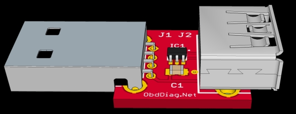
The TPS2514 IC is a USB dedicated charging port (DCP) controller. An auto-detect feature monitors USB data line voltage, and automatically provides the correct electrical signatures on the data lines to charge compliant devices among the following dedicated charging schemes:
- Divider 1 DCP, required to apply 2 V and 2.7 V on the D+ and D– Lines respectively (TPS2513, TPS2514)
- Divider 2 DCP, required to apply 2.7 V and 2 V on the D+ and D– Lines respectively (TPS2513, TPS2514)
- Divider 3 DCP, required to apply 2.7 V and 2.7 V on the D+ and D– Lines respectively (TPS2513A, TPS2514A)
- BC1.2 DCP, required to short the D+ Line to the D– Line
- Chinese Telecom Standard YD/T 1591-2009 Shorted Mode, required to short the D+ Line to the D– Line
- 1.2 V on both D+ and D– Lines
With TPS2514 device implementing the USB charging adapter is simple, see the schematic below. When charging Apple devices the current is limited to 1A as it is implemented Divider 1 charging schema with D+ = 2.0 V and D− = 2.7 V. Also, try to use good quality charging cables. The one particularly bad cable I was using introduced a significant voltage drop forcing my Samsung device switching to the slow charging mode.
Read more: USB CHARGING PORT CONTROLLER USING TPS2514
-
What is the primary function of the TPS2514?
The TPS2514 is a USB dedicated charging port controller that uses an auto-detect feature to monitor USB data line voltage and provide correct electrical signatures. -
How does the chip differentiate between Apple charging modes?
The chip uses specific divider configurations where Divider 1 applies 2.0V on D+ and 2.7V on D-, while Divider 2 applies 2.7V on D+ and 2.0V on D-. -
Can the divider configuration be changed on the fly?
No, Divider 1 or Divider 2 is configured by flipping the connection to USB data lines, meaning it is pre-wired and cannot be changed dynamically. -
Which chips support Divider 3 for Apple charging?
The TPS2514A version specifically supports Apple Divider 3, which requires applying 2.7V on both D+ and D- lines. -
What happens if a bad quality cable is used?
A poor quality cable can introduce significant voltage drop, forcing devices like Samsung phones to switch to a slow charging mode. -
Does the datasheet explicitly mention Samsung or Apple brands?
No, the chip datasheet does not mention Samsung or Apple in particular due to copyright issues, instead referring to them as Divider 1, 2, and 3 modes. -
What voltage levels are required for BC1.2 DCP mode?
BC1.2 DCP requires shorting the D+ Line to the D- Line.

