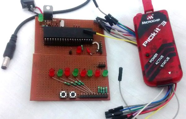
This will be the fifth tutorial in our PIC Tutorial Series, which will help you to learn and use Timers in PIC16F877A. In our previous tutorials, we had started with Introduction to PIC and MPLABX IDE, then we wrote our first PIC program to blink the LED using PIC and then made a LED Blinking Sequence by using delay function in PIC Microcontroller. Now let us use the same LED Blinking sequence which we have used in previous tutorial hardware and with this we will Learn How to use Timers in our PIC MCU. We have just added one more button in LED board for this tutorial. Go through the tutorial to learn more.
Timers are one of the important workhorses for an embedded programmer. Every application that we design will somehow involve a timing application, like turning ON or OFF something after a specified interval of time. Okay, but why do we need timers when we already have delay macros (__delay_ms()) doing the same thing!!
Why Timer when we have Delay() ?
A Delay macro is called a “dump” delay. Because during the execution of Delay function the MCU sits dump by just creating a delay. During this process the MCU cannot listen to its ADC values or read anything from its Registers. Hence it is not advisable to use Delay functions except for applications like LED blinking where the Time delay need not be accurate or long.
The delay macros also has the following short comings,
- The value of delay must be a constant for delay macros; it cannot be changed during program execution. Hence it remains is programmer defined.
- The delay will not be accurate as compared to using Timers.
- Larger values of delays cannot be created using macros, example a delay of half hour cannot be created by delay macros. The maximum delay that can be used is based on Crystal oscillator used.
PIC microcontroller Timers:
Physically, timer is a register whose value is continually increasing to 255, and then it starts all over again: 0, 1, 2, 3, 4…255….0, 1, 2, 3……etc.
The PIC16F877A PIC MCU has three Timer Modules. They are names as Timer0, Timer1 and Timer2. The Timer 0 and Timer 2 are 8-bit Timers and Timer 1 is a 16-bit Timer. In this tutorial we will be using the Timer 0 for our application. Once we understand the Timer 0 it will be easy to work on Timer 1 and Timer 2 as well.
The Timer0 module timer/counter has the following features:
- 8-bit timer/counter
- Readable and writable
- 8-bit software programmable prescaler
- Internal or external clock select
- Interrupt on overflow from FFh to 00h
- Edge select for external clock
To start using a timer we should understand some of the fancy terms like 8-bit/16-bit timer, Prescaler, Timer interrupts and Focs. Now, let us see what each one really means. As said earlier there are both the 8-bit and 16-bit Timers in our PIC MCU, the main difference between them is that the 16-bit Timer has much better Resolution that the 8-bit Timer.
Prescaler is a name for the part of a microcontroller which divides oscillator clock before it will reach logic that increases timer status. The range of the prescaler id is from 1 to 256 and the value of the Prescaler can be set using the OPTION Register (The same one that we used for pull up resistors). For example if the value of prescaler is 64, then for every 64th pulse the Timer will be incremented by 1.
As the timer increments and when it reaches to its maximum value of 255, it will trigger an interrupt and initialize itself to 0 back again. This interrupt is called as the Timer Interrupt. This interrupt informs the MCU that this particular time has lapped.
The Fosc stands for Frequency of the Oscillator, it is the frequency of the Crystal used. The time taken for the Timer register depends on the value of Prescaler and the value of the Fosc.
Programming and Working Explanation:
In this tutorial we will set two buttons as two inputs and 8 LED as 8 outputs. The first button will be used to set the time delay (500ms for every push) and the second button will be used to start the timer sequence blinking. For example, if the first button is pressed thrice (500*3 = 1500ms) the delay will be set for 1.5sec and when the button two is pressed each LED will turn ON and OFF with the predefined time delay. Check the Demonstration Video at the end of this Tutorial.
Now, with these basics into mind let us look at our program given at the end in Code section.
It is okay if you did not get the program, but if you did!! Give yourself a cookie and dump the program to enjoy your output. For others I will break the program into meaningful parts and explain you what is happening in each block.
As always the first few lines of the code are the Configuration settings and header files, I am not going to explain this since I have already did it in my previous tutorials.
Next, let us skip all the lines and jump straight into the void main function, inside which we have the PORT configuration for the Timer0.
void main()
{
/*****Port Configuration for Timer ******/
    OPTION_REG = 0b00000101;  // Timer0 with external freq and 64 as prescalar // Also Enables PULL UPs
    TMR0=100;       // Load the time value for 0.0019968s; delayValue can be between 0-256 only
    TMR0IE=1;       //Enable timer interrupt bit in PIE1 register
    GIE=1;          //Enable Global Interrupt
    PEIE=1;         //Enable the Peripheral Interrupt
    /***********______***********/
The Timer will start incrementing once set and overflow after reaching a value of 256, to enable the Timer interrupt during this point the register TMR0IE has to be set high. Since Timer 0 itself is a peripheral we have to enable the Peripheral Interrupt by making PEIE=1. Finally we have to enable the Global Interrupt so that the MCU will be notified about the Interrupt during any operation, this is done by making GIE=1.
Delay = ((256-REG_val)*(Prescal*4))/Fosc
The above formula is used to calculate the value of Delay.
Where
REG_val = 100;
Prescal = 64
Fosc = 20000000
This on calculation gives,
Delay = 0.0019968s
The next set of lines is to set the I/O Ports.
        /*****Port Configuration for I/O ******/
    TRISB0=1; //Instruct the MCU that the PORTB pin 0 is used as input for button 1.
    TRISB1=1; //Instruct the MCU that the PORTB pin 1 is used as input for button 1.
    TRISD = 0x00; //Instruct the MCU that all pins on PORT D are output
    PORTD=0x00; //Initialize all pins to 0
    /***********______***********/
This is same as that of our previous tutorial since we are using the same hardware. Except that we have added another button as input. This is done by the line TRISB1=1.
Next, inside out infinite while loop we have two blocks of code. One is used to get the timer input from the user and the other to execute the sequence of delay over the LEDs. I have explained them by using comments against each line.
        while(1)
        {
        count =0; //Do not run timer while in main loop
        //*******Get the number delay from user****//////
        if (RB0==0 && flag==0) //When input given
        {
            get_scnds+=1; //get_scnds=get_scnds+1//Increment variable
            flag=1;
        }
        if (RB0==1) //To prevent continuous incrementation
            flag=0;
        /***********______***********/
A variable called get_scnds is incremented each time the user presses the button 1. A flag (software defined) variable is used to hold the incrementing process until the user removes his finger from the button.
                //*******Execute sequence with delay****//////
        while (RB1==0)
        {
                PORTD = 0b00000001<<i;  //Left shit LED by i
                if(hscnd==get_scnds) //If the required time is reached
                {
                    i+=1; //Move to next LED after the defined Delay
                    hscnd=0;
                }
                flag=2;
        }
        if (flag==2 && RB1==1) //Reset timer if button is high again
        {
            get_scnds=0;hscnd=0;i=0;
            PORTD=0; //Turn off all LEDs
        }
        /***********______***********/
The next block gets into action if the button two is pressed. Since the user has already defined the required time delay using button one and it has been saved in the variable get_scnds. We use a variable called hscnd, this variable is controlled by the ISR (Interrupt service routine).
The interrupt service routine is an Interrupt that will be called each time the Timer0 is overflows. Let us see how it is being controlled by the ISR in the next block, like we want to increment the time delay by half second (0.5s) on each button press then we need to increment variable hscnd for every half second. As we have programmed our timer to over flow for every 0.0019968s (~ 2ms), so to count half second count variable should be 250 because 250*2ms = 0.5 second. So when count gets 250 (250*2ms = 0.5 second), means that its been half a second so we increment hscnd by 1 and initialize count to zero.
void interrupt timer_isr()
{
    if(TMR0IF==1) // Timer flag has been triggered due to timer overflow
    {
        TMR0 = 100;     //Load the timer Value
        TMR0IF=0;       // Clear timer interrupt flag
        count++;
    }

    if (count == 250)
    {
        hscnd+=1;   // hscnd will get incremented for every half second
        count=0;
    }
}
So we use this value and compare it to our hscnd and shift our LED based on the user defined time. It is also very similar to last tutorial.
That’s it we have our program understood and working.
Circuit Diagram and Proteus Simulation:
For more detail: Understanding Timers in PIC Microcontroller with LED Blinking Sequence