Summary of Tiny-Dice: Electronic Dice Using an ATtiny2313
The article explains final assembly and testing steps for an electronic dice project using a pre-programmed IC. It advises inspecting solder joints, checking battery polarity and IC socket orientation, powering the board to verify the decimal point LED lights, and debugging if needed. Then disconnect battery, correctly orient and press IC1 into its socket (notch toward battery connection), and reconnect the battery to complete assembly.
Parts used in the Tiny-Dice Project:
- Printed circuit board (assembled)
- Pre-programmed IC1 (ATtiny2313)
- IC socket
- Battery
- Decimal point LED
- Solder and soldering iron
- Various leads and component wires
Final assembly: After assembling all the components on the board make a close inspection of all the joints. Lead/tin solder produces shiny joints; any crazing is an indicator of a dry joint, check for missing solder or solder bridges shorting two tracks together. It’s also worth double checking battery connection polarity and the IC socket orientation. The finished board should look like Figure 3. Now you can connect up the battery but don’t plug in IC1 just yet. The decimal point LED will light up to show that power is available to the board. Should the LED not light then you can begin with what is any engineer’s favorite pastime — hardware debugging. Once everything is okay you can carry on: Disconnect the battery.
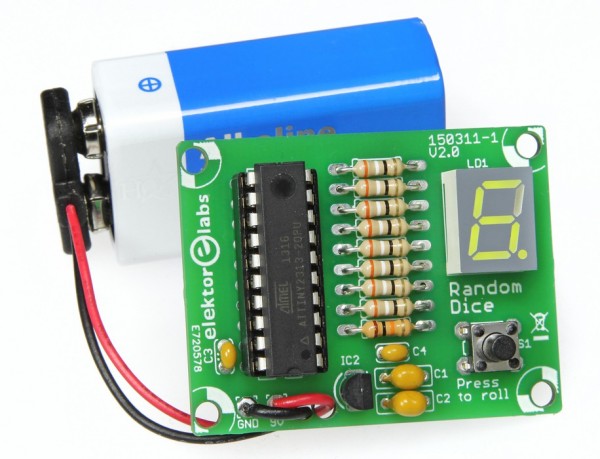
Orientate the pre-programmed IC1 over its socket ensuring that the notch in the package indicating pin #1 is nearest to the battery wire connection point and not the other way round. Check that the package leads line up with all their positions in the socket. Apply light pressure to correct the position of any lead. Now carefully apply pressure evenly to the top of the package using two fingers until the IC is inserted. This may require some force.
Reconnect the battery.
For more detail: Tiny-Dice: Electronic Dice Using an ATtiny2313
- How do I check solder joints after assembly?
Inspect joints for shiny appearance; crazing indicates dry joints and check for missing solder or solder bridges. - What should I verify before powering the board?
Double check battery connection polarity and IC socket orientation. - Why does the decimal point LED light when I connect the battery without the IC?
The decimal point LED lights to show that power is available to the board. - What if the decimal point LED does not light?
Begin hardware debugging to locate faults as recommended in the article. - How should I orient the pre-programmed IC1 when inserting?
Ensure the notch indicating pin 1 is nearest to the battery wire connection point. - How do I insert the IC into the socket?
Line up package leads with socket positions, apply light pressure to correct leads, then press evenly with two fingers until the IC is inserted. - Should the battery be connected when inserting the IC?
No, disconnect the battery before inserting the IC and reconnect it after the IC is seated.