Summary of TIMER RELAY WITH PIC16F88
This article describes an Adaptive Turbo Timer project using a PIC16F88 microcontroller that automatically idles a car engine after hard driving to protect the turbocharger. It adjusts idle duration based on driving intensity and only activates when needed. Schematic, PCB layout, assembly source code, and downloads are provided via referenced links.
Parts used in the Adaptive Turbo Timer:
- PIC16F88 microcontroller
- Timer relay
- Printed circuit board (PCB)
- Power supply components (voltage regulator, capacitors)
- Input sensing components (sensors or pickups to detect engine/turbo state)
- Connectors and wiring for vehicle integration
- Discrete components (resistors, diodes, transistors)
- Programming/debug header for PIC
- Enclosure or mounting hardware
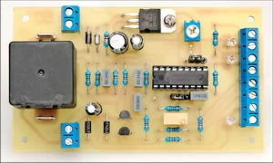
Pic belongs to the timer circuit and printed circuit board circuit diagram drawing software is available. If your car’s turbocharger has just been running, it is vital to allow the engine to idle for a few minutes before switching … Electronics Projects, Timer relay with PIC16F88 ” microchip projects, microcontroller projects, pic16f88 projects,
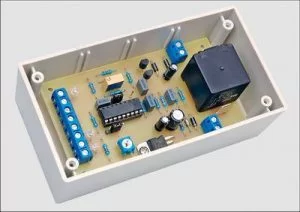
Pic belongs to the timer circuit and printed circuit board circuit diagram drawing software is available.
If your car’s turbocharger has just been running, it is vital to allow the engine to idle for a few minutes before switching off. This Adaptive Turbo Timer will do the job automatically. It only operates when necessary and sets the idle time according to how hard you’ve driving.
TIMER CIRCUIT
Source: http://www.siliconchip.com.au/cms/A_109072/article.html
Timer Circuit schematic pcb PIC16F88 pic assembly source code alternative link:
FILE DOWNLOAD LINK LIST ( in TXT format ): LINKS-2531.zip
Source: TIMER RELAY WITH PIC16F88
- What is the purpose of the Adaptive Turbo Timer?
To automatically keep the engine idling for a calculated time after driving hard so the turbocharger can cool down. - Which microcontroller does the project use?
The project uses the PIC16F88 microcontroller. - Does the timer always run after driving?
No, it only operates when necessary and sets idle time according to how hard you were driving. - Are schematic and PCB files available?
Yes, schematic and PCB files are available and provided via download links referenced in the article. - Is source code provided for the PIC16F88?
Yes, assembly source code for the PIC16F88 is provided via the download links. - Where can I download the project files?
Files are available in a linked archive named LINKS-2531.zip referenced in the article. - Does the project include a relay?
Yes, a timer relay is part of the project as described. - Is this suitable for protecting a car turbocharger?
Yes, the timer is designed to protect the turbocharger by idling the engine for a cooling period.