Summary of THERMOCOUPLE READING CIRCUIT PIC16F877
This article describes a thermocouple reading circuit designed around the PIC16F877 microcontroller. The project includes C source code, Proteus simulation files, Eagle diagrams, and PCB drawings. It utilizes an 8-bit ADC with 10-bit resolution to measure voltage ranges from 0V (0°C) to 42.92mV (760°C), converting temperature differences into proportional millivolt signals at the cold spot.
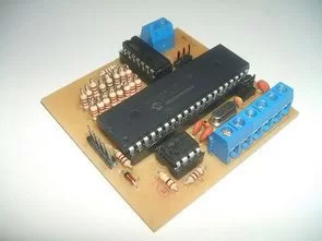
Parts used in the Thermocouple Reading Circuit:
- PIC16F877 microcontroller
- C source software
- ISIS Proteus simulation files
- Eagle diagram
- Printed circuit board drawings
- Thermocouple sensor
Thermocouple reading circuit PIC16F877 microcontroller based on the C source software, isis proteus simulation files and eagle diagram, printed circuit boards have drawings. Thermocouple voltage 0V (0 ° C) and 42.92mv (760 º C)… Electronics Projects, Thermocouple Reading Circuit PIC16F877 “microchip projects, microcontroller projects, pic16f877 projects, “
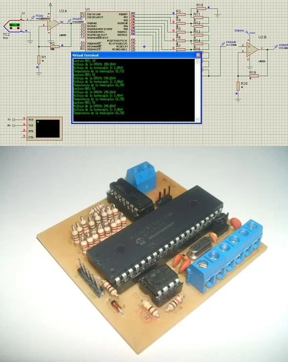
Thermocouple reading circuit PIC16F877 microcontroller based on the C source software, isis proteus simulation files and eagle diagram, printed circuit boards have drawings. Thermocouple voltage 0V (0 ° C) and 42.92mv (760 º C) 4.8mv (5/1024) on a PIC16F877 8-bit resolution ADC resolution 10bits DAC.
THERMOCOUPLE GENERAL INFORMATION
Thermocouples -200 ° to 2320 ° C is widely used in various processes. Thermocouples two different metal alloys, obtained by welding the ends of the temperature measurement element. The point boiled HOT SPOT , the remaining two open ends COLD SPOT is called. With thermocouple cold junction temperature difference between the hot spot is formed. Proportional to the temperature difference voltage in mV at the ends of the cold spot is produced. With hot spot no matter how cold spot temperature distribution of the generated voltage is proportional to the temperature difference between the hot and cold spots
Source: THERMOCOUPLE READING CIRCUIT PIC16F877 alternative link: thermocouple-reading-circuit-pic16f877.rar alternative link2 alternative link3
- What is the voltage range for the temperature measurement?
The circuit measures voltages from 0V corresponding to 0 degrees Celsius up to 42.92mV corresponding to 760 degrees Celsius. - How does the system convert temperature to voltage?
A voltage proportional to the temperature difference between the hot spot and cold spot is produced at the ends of the cold spot. - What resolution does the ADC have in this project?
The PIC16F877 uses an 8-bit ADC with 10-bit resolution capabilities. - Can I simulate this circuit before building it?
Yes, ISIS Proteus simulation files are provided for the project. - Where can I find the design files for the circuit board?
Eagle diagrams and printed circuit board drawings are included in the project package. - Does the generated voltage depend on the cold spot temperature distribution?
No, the generated voltage is proportional only to the temperature difference between the hot and cold spots regardless of distribution. - What programming language is used for the microcontroller?
The project is based on C source software. - What is the function of the DAC mentioned in the text?
The text mentions a DAC as part of the PIC16F877 specifications alongside the ADC resolution.