Summary of The Annoy – A Tiny Intelligent Buzzer using PIC10F202
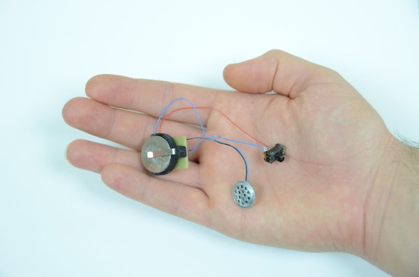
This article details an improved version of "The Annoy," a PIC10F202-based project designed to emit random chirps and buzzes to annoy people. The authors optimized the original design by creating a custom PCB, selecting the smallest SOT23 package for the microcontroller, designing a black enclosure with a switch, and switching to the XC8 compiler for C programming instead of assembly.
Parts used in The Annoy:
- PIC 10F202 (SOT23 package)
- PICKit Programmer
- 1uF Ceramic Capacitor
- 0.47uF Tantalum Capacitor
- Speaker
- CR2032 Battery Holder
- CR2032 Battery
- Copper Clad PC Board
- Ferric Chloride Etchant
- LaserJet Printer
- Glossy Paper
- Solder
- Soldering Iron
- Clothing Iron
A while back I made a blog post about a PIC10F200 Project: The Annoy. In this project they combined the simplicity in design along with the creativeness that I always look for, into a project with no real use other than for fun. However, the project seemed a little too large and we felt we could improve upon it, so let’s get to it!
In this article we will take a look at the original, ‘The Annoy’ project, and see what we can do to improve it. Specifically, we’ll make a PCB for the project, find the smallest PIC package available for it and make a nice enclosure for it. Additionally, we’ll switch over and use microchip’s new XC8 compiler so we don’t have to use assembly for programming.
Purpose & Overview of this project
The goal of this project is to build something that is annoying and borderline tortuous. To do that we will use a microcontroller and a speaker to generate some chirping and buzz-like noises every few minutes in order to slowly drive people nearby insane.
To build this project, we will use a 10F202 PIC microcontroller. It will output some sounds to a speaker to create the chirping noises and then use internal pauses to wait a few minutes before outputting the next chirp or buzz. To conceal the project, we’ll make a small black enclosure and add an on/off switch.
PICKit Programmer
1uF Ceramic Capacitor
0.47uF Tantalum Capacitor
Speaker
CR2032 Battery Holder
CR2032 Battery
Copper Clad PC Board
Ferric Chloride Etchant
LaserJet Printer
Glossy Paper
Solder
Soldering Iron
Clothing Iron Iron
Parts List Details
Luckily this project is more software based than hardware so there’s not many components. The more important components are described in more detail below.
PIC 10F202 (SOT23 package)
This is the microcontroller that we’re going to use to generate the bzzz or chirp noises through the speaker. It’s a super tiny SOT23 6 pin package so it will barely be visible once soldered into the circuit.
PICKit Programmer
To put the program onto the PIC, we’re going to need a programmer. To do that job I’ve chosen to use a microchip PICKit programmer. It will load the .hex file onto the PIC10F202.
Copper Clad PC Board
For this project we’re going to be making our own PCB so we’ll need some copper clad PC board. We’ll use etchant to eat away the extra copper after transferring toner from some glossy paper to get our circuit design onto this board.
Speaker
We don’t need a fancy speaker here, just something small that does the job. The smaller the better, but we’ll still want it to be loud, so make sure its a decent quality speaker. You could also use a buzzer, but then the sound would always remain the same tone & pitch.
Schematic Overview
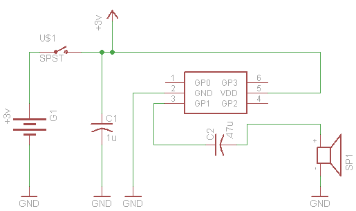
The schematic shown below is just as simple as it seems to be. This project is based upon the premise of using as little parts as possible to be as annoying as possible 🙂 so its kept super duper simple!
Schematic Specifics
PIC10F202
The main processor for this board is the PIC10F202 which is a tiny microcontroller in a SOT-23 package with 6 pins (it’s not labeled on the schematic–doh!, but I think its obvious which 6 pin part we’re talking about). Although we’re only actually using 3 of the pins: power, ground and output to the speaker.
Capacitors
Two capacitors are used in this design. The first capacitors is across the power and ground connections to make sure the PIC has enough current to operate nominally. The second capacitors appears before the speaker. This will increase the volume of the speaker a little bit.
Speaker
The speaker that we’ll use is a generic ear-bud style speaker that we’ve cut off of a set of headphones. The PIC can’t output too much current so don’t expect it to drive an 8Ω speaker and be really loud, use some small ear-bud speakers like we did.
For more detail: The Annoy – A Tiny Intelligent Buzzer using PIC10F202
- What is the main purpose of this project?
The goal is to build something annoying that uses a microcontroller and speaker to generate chirping and buzzing noises every few minutes. - Which microcontroller is used in this design?
The project utilizes a PIC 10F202 microcontroller in a tiny SOT23 6-pin package. - Can I use a standard buzzer instead of a speaker?
You could use a buzzer, but the sound would always remain the same tone and pitch compared to a speaker. - How do I program the microcontroller?
The article suggests using Microchip's new XC8 compiler for C programming or a PICKit programmer to load the .hex file. - What type of capacitors are required for the circuit?
The design requires one 1uF ceramic capacitor across power and ground, and one 0.47uF tantalum capacitor before the speaker. - How is the custom PCB manufactured in this project?
The PCB is made by transferring toner from glossy paper printed on a LaserJet printer to copper clad board and etching it with ferric chloride. - What kind of speaker works best for this project?
A small ear-bud style speaker cut from headphones is recommended because the PIC cannot drive an 8Ω speaker loudly. - Does the device have a way to turn it off?
Yes, the project includes a small black enclosure with an on/off switch.