Summary of Sunrise Alarm Clock
This article details the design and construction of a programmable sunrise alarm clock. It utilizes a full-spectrum LED to simulate natural sunlight for a gentle wake-up, complemented by a backup audio alarm. The system features a physical user interface with buttons and a rotary encoder, alongside remote control via a Bluetooth phone app. Key components include an RTC chip for timekeeping during power outages and an EEPROM for storing alarm settings. The project successfully balances hardware debouncing with software logic to ensure reliable operation, offering a restful alternative to traditional alarms.
Parts used in the Sunrise Alarm Clock:
- PIC32 microcontroller
- HM10 Bluetooth module clone
- DS3231 high precision RTC chip
- Lithium coin cell battery
- EEPROM memory chip
- Seoul Semiconductor SunLike full spectrum LED
- ODLC-45 Meanwell LED driver
- Sunon LED heatsink with integrated 12V fan
- 240x320 pixel TFT display
- Piezo buzzer
- Two momentary switch buttons
- Rotary encoder with button
Introduction
This report covers the design and building of a programmable alarm clock that uses a full spectrum LED to wake you up using your body’s natural response to sunlight. Rather than waking you up with an annoying alarm, a sunrise alarm clock slowly turns on a light in your room over the course of about an hour or so to simulate a natural sunrise. This allows your body to naturally wake up when it reaches the end of its current REM cycle rather than having in the middle of such a cycle (which can make waking up difficult and be disorienting). If you are still asleep at the end of the sunrise cycle, a back up audio alarm goes off to wake you up. Using a sunrise alarm clock can lead to more restful sleep, a gentler wake up experience, and make it more likely you actually stay up after waking up. For the busy student, a sunrise alarm clock can mean the difference between waking up peacefully for class, or missing class entirely after shutting off their traditional alarm and falling right back asleep without even realizing it.
High level design:
Design Requirements:
This iteration of a sunrise alarm clock had several design parameters. It needed to have a full spectrum LED to mimic sunlight. This was intended to create a pleasing light, but also to help combat Seasonal Affective Disorder. Another important thing for the LED was that it used analog dimming. PWM dimming can create an annoying flicker and we wanted a smooth light viewing experience. It would also be awesome to be able to use this fancy LED during the day or night without the the alarm functionality. We ended up calling this a “night light mode” because you could use the alarm as a “night light” if you needed to.
It also needed a backup audio alarm in case the sunrise wasn’t enough to wake you up. In this project this is a simple piezo buzzer that is very annoying and is sure to wake even the heaviest of sleepers up. For the user interface it needed to have a physical control interface. An LCD screen with buttons for sure. We ultimately decided to stick with the TFT we have been using in the lab. We also decided on a 2 button and a rotary encoder with button design for the user controls. This would allow anybody to use the alarm clock just by walking up to it and twiddling with the dials.
In addition to the physical interface, remote control of the system via a phone app through a bluetooth connection was also added. This way, you can set the alarm for the morning without having to get out of bed.
One final requirement is that the alarm clock should remember the alarm and also keep track of time even if it loses power (such as by being unplugged, or through a power outage). There is nothing worse than having a power surge in the middle of the night and oversleeping and being late because your alarm doesn’t go off in the morning. An RTC chip and EEPROM for alarm storage with on board battery backup solves both of these issues.
Logical Structure:
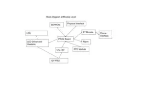
Below you can see a high level block diagram of the system as it is now. The PIC32 is the brain of the system and interacts with the different “modules” of the system. In the block diagram below you can see how we separated out the different modules in our design. We were able to then test each of these modules individually and put them together in the final build.
Hardware/Software Tradeoffs:
One thing that we wanted to implement in our system was hardware based input debouncing. This would make the software side of the system a lot easier to run since we would already be working with clean inputs and don’t require additional state machines to debounce the switches. However this complicates the hardware side a bit which is the tradeoff. Since we utilized software debouncing in an earlier lab this semester, we decided to try and do the hardware version.
Hardware Design
The hardware for this project can be subdivided into several submodules. We have the UART bluetooth interface, the I2C devices, the LED systems and alarm, and the user interface.
Bluetooth:
For this project we used an HM10 Bluetooth module clone (image). These modules make bluetooth connection very easy by acting as a simple serial passthrough. The PIC will send serial data to the bluetooth module, and any devices connected will receive that data via bluetooth. Any data that gets sent to the HM10 then is passed on to the PIC via UART. The HM10 module does all the heavy lifting for us.
On the control side of things we are able to use almost any modern phone to connect to this bluetooth module to control our alarm clock.
I2C:
We have two I2C slave devices in this project and they both happen to be on the same peripheral board. The DS3231 is a high precision RTC chip with temperature compensation. Using this device allows us to always have the time and continue to keep track of the time even when the alarm clock is unplugged thanks to a lithium coin cell which keeps it going. This peripheral board was connected to the clock and data lines of the PIC32’s I2C1 channel.
LED System:
There were two primary design goals of the LED system of this alarm clock. The first was to use a full spectrum LED to simulate natural sunlight, and the second was to implement analog dimming to avoid that annoying PWM flicker. The Seoul Semiconductor SunLike line of LEDs contain phosphors which combined with a violet LED are able to replicate the sun’s spectrum very closely compared to traditional LEDs. The hope is that this replication of sunlight will wake up your body easier and also help with SAD during the dark winter months in New York.

image courtesy of Seoul Semiconductor
Driving this LED is no easy task, it has a typical forward voltage of 36V so we need a fairly beefy power supply to get it working. The ODLC-45 from Meanwell is able to easily drive this LED and also has a built-in analog dimming functionality taking a 10V PWM input signal. The duty cycle of the PWM signal determines the current that the LED runs at.
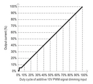
image from the ODLC-45 datasheet
In addition to a driver we also need a heatsink for this large LED, so a simple Sunon LED heatsink with integrated 12v fan was used.
For the audio alarm, a simple piezo buzzer is used, it is loud and annoying enough to get anybody to wake up from sleep.
User Interface
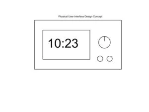
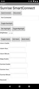
The user interface consists of the display and the controls. We simply used the 240×320 pixel TFT that was provided at the beginning of the course. The controls consisted of two momentary switch buttons and a rotary encoder/button combination. Below is a picture of the UI concept we had planned.
One of the things that we wanted to do was implement hardware debouncing in this circuit. This would allow us to simplify the coding process since we wouldn’t need to debounce in software.
The hardware debounce is achieved through an RC network which basically smooths over the bounces. This classic charging curve is then fed into a schmitt trigger which creates a very sharp cutoff and outputs a clean signal which is then connected to the external interrupt pins.
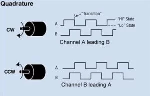
The rotary encoder uses quadrature encoding. When the rotary encoder is turned, two pulses are emitted, each on a separate channel. If the rotary encoder is turning clockwise, the pulse on channel A leads the one on channel B. If it is turning counter clockwise the pulse on channel B leads the one on channel A. By noting which signal is detected first, the direction of rotation can be determined.
Program Design
The program that controls the alarm clock is broken into multiple protothreads. Some of these threads run continuously while others wait for a flag to change or only run in a specific state. In addition to the protothreads, each of the user interface buttons has an associated ISR that is used to toggle flags to indicate that a button has been pressed.
Protothreads:
Control Thread
This thread controls the state of every flag that doesn’t directly indicate that the state of a button or rotary encoder has changed (these flags are set in the button ISRs). The control thread is essentially a finite state machine that changes state based on the state of the flags that indicate whether the buttons have been pressed. It differs from a pure finite state machine because there are some flags that are not tied to the current state. A finite state machine seemed like the simplest choice for this thread because it allowed the effect of every button to be enumerated for every state that the clock could be in. The button flags have different behavior depending on the current state of the control thread: for example, when the TFT is displaying the default clock screen, the rotary encoder button has the effect of toggling night light mode, but when the TFT is displaying the settings screen, the rotary encoder button instead has the effect of selecting a setting to change.
Night Light Thread
This thread controls the light night mode of the alarm clock and only runs if night light mode is enabled. Night light mode lets you use the LED as a light source without needing to set an alarm, and this thread manages the dimming level of the LED and whether or not the LED is on at all.
Sunrise Thread
This thread checks the status of the sunrise mode flag. If the flag is enabled, it sends a pulse-width modulated signal to the sunrise LED, with the duty cycle of this signal being determined by the formula: 400000-(Ts*40000)/Ls with Ts being the time in seconds remaining in the sunrise and Ls being the length in seconds of the full sunrise. This has the effect of increasing the intensity of the LED linearly from zero to its maximum as time progresses from the start of the sunrise to the alarm time.
Audio Alarm Thread
If the alarm audio is enabled and the alarm is currently activated, this thread toggles the pin that controls the audio output every 500 milliseconds to produce a sound that will wake the user up if the sunrise has failed (or was not enabled).
Update Time Thread
This thread runs every 100 milliseconds. It first calls a function that queries the RTC module for the current time. Then, if the returned time is different from the currently displayed time, it updates the TFT display. If an alarm is enabled the thread checks for a match between the current time, the sunrise start time, and the alarm time. If either of the latter two match the former, then the flags for starting the sunrise or starting the alarm sound are set depending on what alarm settings have been enabled.
BT Serial Thread
The BT serial thread only activates when a serial command is received. Its job is to parse the command and perform any operations if required. There are currently 6 commands that it recognizes.
- Toggling the TFT Backlight
- Toggling the alarm enable
- Set alarm to the received data
- Send out alarm data
- Set the night light level
- Toggle the Night Light
- With these commands, the associated phone app is able to control the alarm clock remotely.
Interrupt Service Routines:
The interrupt service routines for the buttons were very simple. All they did was set two global flags and clear the interrupt. They set the flag for their associated button and also the flag for an input change which activates the control thread.
The interrupt service routines for the rotation of the rotary encoder were a bit more complex. They need to first check the flag for the other rotary encoder channel to see if the interrupt for the other channel was triggered first. If it was, then the ISR knew the direction of rotation and saved it. If it did not see that the other channel was triggered, it would simply set the flag for its own channel and clear the interrupt.
One additional check needs to happen though. It can occasionally happen that the inputs are misread if the rotary encoder is spun too quickly, and one of the pulses gets missed. When this happens suddenly the program thinks the encoder is spinning the other direction since it thinks the other channel arrived first. This is solved by making the ISR check how long it has been since the last interrupt, and if it is greater than the timeout, 100ms in this case, it simply resets both rotary encoder flags to ensure the correct direction is read in the future.
Main Program
The purpose of the main function is simply to set up all the input and output pins, activate the serial and I2C channels, and intialize and start the protothreads.
Phone App:
The phone app was programmed using MIT App Inventor. This allowed a rapid development of the basic functionality required. The phone app is basically a wrapper for the serial commands that can be sent to the serial thread through the bluetooth module:
- Toggling the TFT Backlight
- Toggling the alarm enable
- Set alarm to chosen settings
- Get the current alarm data
- Set the night light level
- Toggle the Night Light
I2C Utility Functions
The I2C communication with the RTC module and EEPROM uses the communication patterns defined in the spec sheets for those components. The PIC32 has I2C communication functions and status bits defined in the legacy peripheral librariesThe main problem encountered when sending bytes to the I2C modules from the PIC32 was difficulty checking for acknowledgement from the modules. This was solved by waiting for the transaction to be complete before checking acknowledgement (this is not done by default when acknowledgement is checked). The PIC32 likely was checking for acknowledgement before the transaction was complete (plausible considering that the PIC32’s clock is many times faster than the selected I2C clock).
Several utility functions were written in order to make communication with these two modules easy. Since only four types of transactions (set RTC time, retrieve RTC time, save bytes to EEPROM, retrieve bytes from EEPROM) were ever performed, a function was written for each transaction and stored in a file that was included in the main file.
Results of the Design:
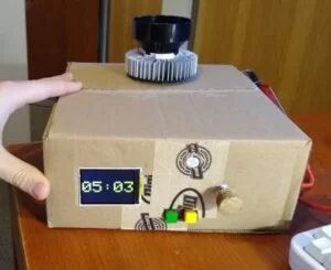
Our alarm clock system works very well. The user interface functions exactly as intended, and the buttons are effectively debounced. The phone app works just as intended as well. You can lay in bed and change the alarm settings as desired. A cardboard box enclosure was used for simplicity and to reduce cost. The LED heatsink stays cool and only gets slightly warm when the LED is powered on at full power for extended periods of time.
For a demo of the alarm clock watch the video below:
One other thing of note: It is possible for the time value of the clock to be incorrect for a fraction of a second. This is because the PIC32 polls for the current time every tenth of a second and then updates the displayed time on the TFT. If a time update occurred on the RTC module immediately after it was polled for the time, the value on the clock would be incorrect until the next poll occurred and was displayed. The below diagram illustrates an example of this behavior: the “clk” line is a simple clock that toggles from 0 to 1, the “poll” line represents the polling of the RTC by the PIC32 (occuring at a different frequency than the clock), and the “disp” line represents the displayed value on the TFT. With an ideal clock, the value of the disp line would always match that of the clk line, but because of the limited nature of the polling, this is not true in several regions on the diagram. This is an extreme example of innacuracy rising from polling, and it would be greatly reduced in severity by polling at a higher frequency than the clock, but it successfully illustrates the phenomenon.
Conclusions:
This design and final product met all of the required needs of our sunrise alarm clock specifications. Our goal was to create an alarm clock that emulated the rising of the sun in order to wake up the user, and our project achieves that. It is easy to use, the phone app works seamlessly, and this alarm clock is likely to be used for a long time going into the future.
It wasn’t all perfect though. In order to reach this point we did have to cut out some original intended features. In our proposal we had planned to have 5 separate programmable alarms that were stored in the eeprom. We also planned on being able to set which days of the week they would activate and reset automatically. Due to time constraints this more advanced alarm clock feature was cut to make sure we got a functioning unit at the end our our project.
Another interesting thing that we had happen had to do with the rotary encoder. When spun quickly, it is possible for the PIC32 to miss a pulse due to the debouncing circuit and make the PIC32 think the encoder has been spun in the opposite direction to the actual spin. This is a limitation of the quadrature encoding. The original plan was to utilize a grey code based encoder where this type of error is far less likely to happen. However due to an ordering error and again a time limitation, we needed to make do with the encoder we had.
Overall this project turned out to be success and while our end product is missing a feature or two, it still functions excellently and will be used for a long time.
Appendix A: Releases
The group approves this report for inclusion on the course website.
The group approves the video for inclusion on the course youtube channel.
Appendix B: Commented program listing
The program consists of the source files below:
Config_1_3_2.h
Glcdfont.c
Pt_cornell_1_3_2.h
Tft_gfx.h
Tft_gfx.c
Tft_master.h
Tft_master.c
Control.h
Control.c
Data.h
Data.c
I2c.h
I2c.c
types.h
Main.c
Screens.h
Screens.c
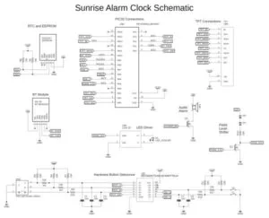
Appendix C: Schematic
Source: Sunrise Alarm Clock
- How does the sunrise alarm clock wake you up?
It slowly turns on a full spectrum LED over about an hour to simulate a natural sunrise. - What is the purpose of the analog dimming feature?
Analog dimming is used to avoid the annoying flicker associated with PWM dimming. - Does the alarm keep track of time if it loses power?
Yes, the DS3231 RTC chip with a lithium coin cell keeps track of time even when unplugged. - Can you control the alarm clock using a phone?
Yes, you can set the alarm remotely via a phone app connected through a Bluetooth HM10 module. - What happens if the sunrise light is not enough to wake you up?
A backup piezo buzzer activates as an audio alarm to ensure you wake up. - Why was hardware debouncing chosen for the switches?
Hardware debouncing simplifies the software by providing clean inputs without needing additional state machines. - How does the system determine the direction of the rotary encoder?
It uses quadrature encoding where the order of pulses on channel A and B determines clockwise or counter-clockwise rotation. - What formula controls the LED intensity during the sunrise cycle?
The duty cycle is determined by the formula 400000-(Ts*40000)/Ls to increase intensity linearly. - Which tool was used to program the phone app?
The MIT App Inventor was used to rapidly develop the basic functionality of the phone app. - What limitation exists regarding the time display accuracy?
The displayed time may be incorrect for a fraction of a second due to the polling frequency of the RTC.