Summary of SPI to 4 x UART Bridge (MULTIUART)
This article details a DIY SPI to 4x UART bridge project, enabling microcontrollers with limited serial ports to communicate with up to four external devices simultaneously using the faster SPI interface. The design utilizes a PIC24FJ64GA306 microcontroller to manage multiple UART peripherals, ideal for projects requiring GPS, GSM, or Bluetooth connectivity on affordable hardware.
Parts used in the SPI to 4 x UART Bridge:
- PIC24FJ64GA306 Microcontroller
- 10uF Ceramic Capacitor
- Four 100nF Ceramic Capacitors
- Two 10K Resistors
- One 330R Resistor
- LED Indicator
- PCB Board
- Two 8-way SIL Headers (2.54mm pitch)
- Six-way SIL Header (2.54mm pitch)
- PICkit 3 Programmer
If your a fan of electronics then you like me will often find it annoying on the lack of hardware serial ports on modern devices. Many modules like the Wifi ESP8266 and the Bluetooth HC-06 are available for peanuts but they each require a UART based serial peripheral on your controller to work effectively. In fact a huge range of external electronics can be added to your system via a serial UART connection: GPS, GSM (mobile phone), RFID, RS232, LIN, Ethernet, Zigbee, Modbus, DMX, 4D systems graphical LCDs to name a few more.
Most modern microcontrollers and devices like the Raspberry Pi have at least one serial UART peripheral so you can do a lot with these devices. However now and then you need to combine several communications style modules together into a single design. A recent project I undertook was a mobile alarm system which used Bluetooth proximity to arm / disarm the system, GPS to track the location, Accelerometer to track movement and GSM based SMS messages to inform the owner where their item is.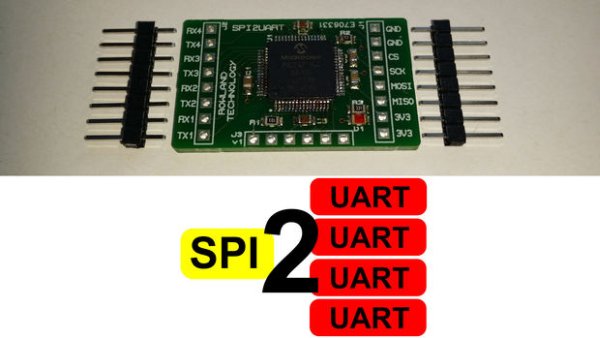
The Arduino Mega 2560 offers two serial UART peripherals but what if that is not enough or you need something more affordable for mass production. To move to a different chip may mean rewriting your entire code so is there an easier way?
These modern microcontrollers commonly also feature a peripheral named SPI which is typically a lot faster then a UART based serial peripheral and can be used to talk to multiple devices by use of individual chip select signals from the controller. If the controller does not have an SPI peripheral then it can simply be driven using a bit banged software approach using standard I/O pins with no major downfalls. By using the SPI interface and my design you can communicate with up to four serial UART peripherals simultaneously.
Here is a guide to recreate and build my SPI to 4 x UART bridge for use in your own projects. If you don’t want to make your own then I also have a limited number of assembled boards available.
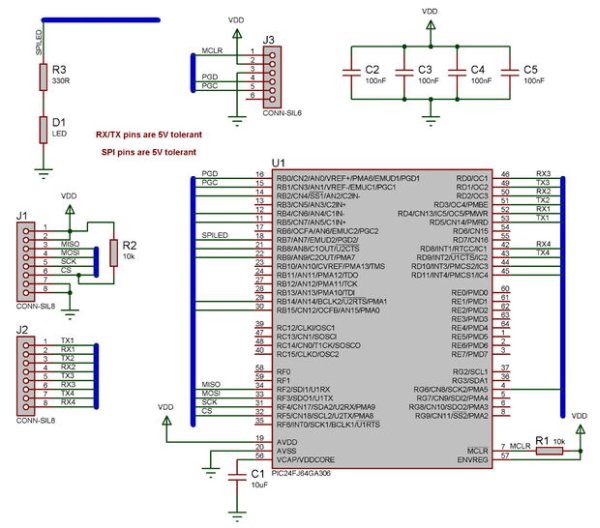
Step 1: The schematic
The circuit for the board is pretty basic as we are simply using a larger 16-bit PIC micro controller to do most of the work for us.
U1 is the PIC24FJ64GA306 micro controller, I chose this chip because it has four UART peripherals and was the cheapest I could find by shopping around on Farnell and microchipdirect. The chip also features several 5V tolerant I/O pins meaning that even though the device will need to be powered at 3.3V it will work as is with 5V systems.
C1 is a 10uF ceramic capacitor and is required by the micro controller to maintain the internal processor voltage levels. This capacitor need to be placed close to the VCAP pin.
C2, C3, C4 and C5 are 100nF ceramic capacitors to provide some voltage smoothing and noise rejection to allow the micro controller to run reliably. These capacitor need to be placed close to the VSS and VDD pins of the micro controller.
R1 provides the MCLR reset signal allowing the micro controller to run. R2 pulls the chip select signal high by default so the SPI interface is automatically disabled until driven low by the host. R3 is a current limiting diode to drive the communications indicator LED.
J1 is the interface to the host controller. It provides connections such as power (3.3V) and ground as well as the four standard SPI pins (MOSI, MISO, SCK and CS). J2 is the interface to the four serial UART peripherals. J3 is the in circuit serial programming (ICSP) header designed to work with the PICkit 3 programming tool.
Note that if your designing your own board then you might want to include other features to be accessed via the SPI interface.
Step 2: The bill of materials
Here is a list of the materials I used in the project.
- 1 x PIC24FJ64GA306
- 2 x 8 way SIL headers 2.54mm pitch
- 2 x 10K Resistor
- 1 x 330R Resistor
- 1 x 10uF Ceramic Cap
- 4 x 100nF Ceramic Cap
- 1 x LED
- 1 x PCB
Also required for the build
- 1 x PICkit 3 programmer
- 1 x 6 way SIL header 2.54mm pitch
- Host controller with SPI interface for testing (I used an ECIO28P from MatrixTSL, an Arduino would also be fine)

Step 3: The PCB
The PCB was created using Proteus and standard 0805 sized surface mount components. Eagle would work just as well if you are familiar with that.
The PCB design was exported as a series of Gerber files and manufactured using Eurocircuits. The Gerber files are attached in the zip file.
The trick with Eurocircuits is to order in bulk to bring down the price per board. So make sure your circuitry is correct before submitting your design. Of course any other PCB manufacturer should also be able to work with the Gerber files.
I ordered my PCBs with a top layer surface mount mask to make the manufacturing process easier. I created a jig for the PCBs to sit in by using my trusty CNC machine to create a pocket in a piece of MDF. The pocket needs a small cut out to ensure you can get it out of the hole easily. I placed a PCB into the pocket and used this to line up the solder paste mask. Once the mask is in place use tape to secure one side of the mask to the MDF. This creates a hinge so you can easily lift up the mask to add or remove the PCBs.
To create the code to drive the CNC I used SketchUp to draw a square the size of my PCB. I then added a small slot to make removing the PCB from the pocket easier. The file was then saved and exported as a .dxf CAD file. I then used the LazyCAM software to convert the .dxf file into G-code which will drive my CNC machine.
For more detail: SPI to 4 x UART Bridge (MULTIUART)
- How many UART peripherals can this bridge support?
The design allows communication with up to four serial UART peripherals simultaneously. - What microcontroller is used in this project?
The project uses the PIC24FJ64GA306 microcontroller which features four UART peripherals. - Can this circuit work with 5V systems?
Yes, the chip has 5V tolerant I/O pins allowing it to work with 5V systems despite being powered at 3.3V. - What software was used to create the PCB design?
The PCB was created using Proteus and exported as Gerber files for manufacturing. - How was the solder paste mask aligned during assembly?
A jig made from an MDF pocket created by a CNC machine was used to line up the solder paste mask. - Which tool is required to program the microcontroller?
A PICkit 3 programming tool is required to program the chip via the ICSP header. - What host controllers are suitable for testing this board?
Any host controller with an SPI interface works, such as an ECIO28P or an Arduino. - Why was the PIC24FJ64GA306 chosen for this design?
It was selected because it has four UART peripherals and was the cheapest option found.